Chapter: Basic Electrical : Electrical Machines
Transformer
Transformer
A
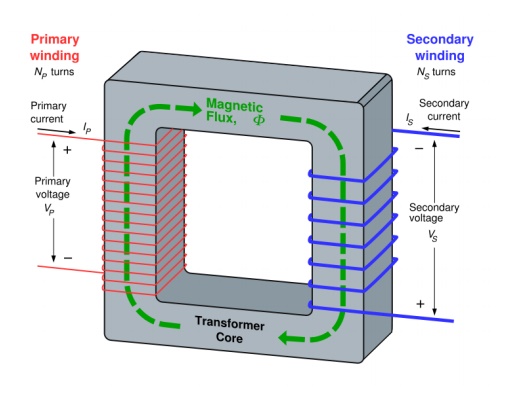
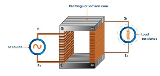
transformer transfers electrical energy between two circuits. It usually
consists of two wire coils wrapped around a core. These coils are called
primary and secondary windings. Energy is transferred by mutual induction
caused by a changing electromagnetic field. If the coils have different number
of turns around the core, the voltage induced in the secondary coil will be
different to the first.

The
device which is used to stepping up or stepping down of voltages is known as transformer.
For transformer
working principle and its uses:

Equivalent circuit:
The
physical limitations of the practical transformer may be brought together as an
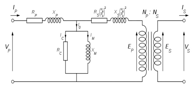
equivalent circuit model built around an ideal lossless transformer. Power loss
in the windings is current-dependent and is represented as in-series
resistances RP and RS. Flux leakage results in a fraction
of the applied voltage dropped without contributing to the mutual coupling, and
thus can be modelled as reactance of each leakage inductance XP and
XS in series with the perfectly coupled region.
Iron
losses are caused mostly by hysteresis and eddy current effects in the core,
and are proportional to the square of the core flux for operation at a given
frequency. Since the core flux is proportional to the applied voltage, the iron
loss can be represented by a resistance RC in parallel with the ideal
transformer.
A core with finite permeability requires a magnetizing current IM to maintain the mutual flux in the core. The magnetizing current is in phase with the flux; saturation effects cause the relationship between the two to be non-linear, but for simplicity this effect tends to be ignored in most circuit equivalents. With a sinusoidal supply, the core flux lags the induced EMF by 90° and this effect can be modeled as a magnetizing reactance (reactance of an effective inductance) XM in parallel with the core loss component. RC and XM are sometimes together termed the magnetizing branch of the model. If the secondary winding is made open-circuit, the current I0 taken by the magnetizing branch represents the transformer's no-load current.
The secondary impedance RS
and XS is frequently moved to the primary side after multiplying the
components by the impedance scaling factor (NP/NS)2

Transformer equivalent circuit,
with secondary impedances referred to the primary side
The
resulting model is sometimes termed the "exact equivalent circuit",
though it retains a number of approximations, such as an assumption of
linearity. Analysis may be simplified by moving the magnetizing branch to the
left of the primary impedance, an implicit assumption that the magnetizing
current is low, and then summing primary and referred secondary impedances,
resulting in so-called equivalent impedance.
Application of transformer:
Transformers
are frequently used in power applications to interconnect systems operating at
different voltage classes, for example 138 kV to 66 kV for transmission.
Another application is in industry to adapt machinery built (for example) for
480 V supplies to operate on a 600 V supply. They are also often used for
providing conversions between the two common domestic mains voltage bands in
the world (100-130 and 200-250). The links between the UK 400kV and 275kV
'Super Grid' networks are normally three phase autotransformers with taps at
the common neutral end.
On long
rural power distribution lines, special autotransformers with automatic
tap-changing equipment are inserted as voltage regulators, so that customers at
the far end of the line receive the same average voltage as those closer to the
source. The variable ratio of the autotransformer compensates for the voltage
drop Voltage drop along the line.
In audio
applications, tapped autotransformers are used to adapt speakers to
constant-voltage audio distribution systems, and for impedance matching such as
between a low-impedance microphone and a high-impedance amplifier input.
Related Topics