Chapter: Basic Electrical : Electrical Machines
DC Motor
DC Motor
DC Motor:
A DC
motor is a device which converts electrical energy into mechanical energy.D.C.
motors are motors that run on Direct Current from a battery or D.C. power
supply. Direct Current is the term used to describe electricity at a constant
voltage. A.C. motors run on Alternating Current, which oscillates with a fixed
cycle between a positive and negative value. Electrical outlets provide A.C.
power.
In a brushed
DC motor, the brushes make mechanical contact with a set of electrical contacts
provided on a commutator secured to an armature, forming an electrical circuit
between the DC electrical source and coil windings on the armature. As the
armature rotates on an axis, the stationary brushes come into contact with
different sections of the rotating commutator.
Permanent
magnet DC motors utilize two or more brushes contacting a commutator which
provides the direct current flow to the windings of the rotor, which in turn
provide the desired magnetic repulsion/attraction with the permanent magnets
located around the periphery of the motor.
The
brushes are conventionally located in brush boxes and utilize a U-shaped spring
which biases the brush into contact with the commutator. Permanent magnet
brushless dc motors are widely used in a variety of applications due to their
simplicity of design, high efficiency, and low noise. These motors operate by
electronic commutation of stator windings rather than the conventional
mechanical commutation accomplished by the pressing engagement of brushes
against a rotating commutator.
A
brushless DC motor basically consists of a shaft, a rotor assembly equipped
with one or more permanent magnets arranged on the shaft, and a stator assembly
which incorporates a stator component and phase windings. Rotating magnetic
fields are formed by the currents applied to the coils.
The
rotator is formed of at least one permanent magnet surrounded by the stator,
wherein the rotator rotates within the stator. Two bearings are mounted at an
axial distance to each other on the shaft to support the rotor assembly and
stator assembly relative to each other. To achieve electronic commutation,
brushless dc motor designs usually include an electronic controller for
controlling the excitation of the stator windings.
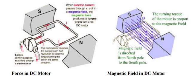
How DC motors work?
There are
different kinds of D.C. motors, but they all work on the same principles.When a
permanent magnet is positioned around a loop of wire that is hooked up to a
D.C. power source, we have the basics of a D.C. motor. In order to make the
loop of wire spin, we have to connect a battery or DC power supply between its
ends, and support it so it can spin about its axis. To allow the rotor to turn
without twisting the wires, the ends of the wire loop are connected to a set of
contacts called the commutator, which rubs against a set of conductors called
the brushes. The brushes make electrical contact with the commutator as it
spins, and are connected to the positive and negative leads of the power
source, allowing electricity to flow through the loop. The electricity flowing
through the loop creates a magnetic field that interacts with the magnetic field
of the permanent magnet to make the loop spin.
Principles of Operation:
It is
based on the principle that when a current-carrying conductor is placed in a
magnetic field, it experiences a mechanical force whose direction is given by
Fleming's Left-hand rule and whose magnitude is given by
Force, F
= B I l newton
Where B
is the magnetic field in weber/m2.
I is the
current in amperes and
l is the
length of the coil in meter.
The
force, current and the magnetic field are all in different directions.
If an
Electric current flows through two copper wires that are between the poles of a
magnet, an upward force will move one wire up and a downward force will move
the other wire down.
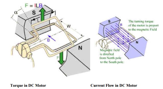
Torque in DC Motor Current
Flow in DC Motor
Classification of motor:
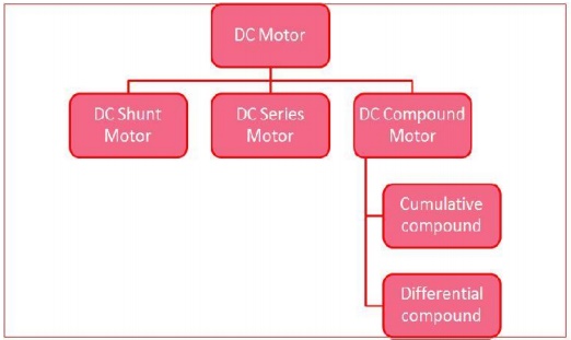
DC motors
are more common than we may think. A car may have as many as 20 DC motors to
drive fans, seats, and windows. They come in three different types, classified
according to the electrical circuit used. In the shunt motor, the armature and
field windings are connected in parallel, and so the currents through each are
relatively independent. The current through the field winding can be controlled
with a field rheostat (variable resistor), thus allowing a wide variation in
the motor speed over a large range of load conditions. This type of motor is
used for driving machine tools or fans, which require a wide range of speeds.
In the
series motor, the field winding is connected in series with the armature
winding, resulting in a very high starting torque since both the armature
current and field strength run at their maximum. However, once the armature
starts to rotate, the counter EMF reduces the current in the circuit, thus
reducing the field strength. The series motor is used where a large starting
torque is required, such as in automobile starter motors, cranes, and hoists.
The
compound motor is a combination of the series and shunt motors, having parallel
and series field windings. This type of motor has a high starting torque and
the ability to vary the speed and is used in situations requiring both these
properties such as punch presses, conveyors and elevators.
DC motor advantages:
Easy to
understand design
Easy to
control speed
Easy to
control torque
Simple,
cheap drive design
Related Topics