Chapter: Electrical Engineering and Instrumentation : Transformer
Transformer on Load
Transformer on Load
The
transformer is said to be loaded, when its secondary circuit is completed
through an impedance or load. The magnitu de and phase of secondary current
(i.e. current flowing through secondary) I2 with respect to
secondary terminals depends upon the characteristic of the load i.e. current I2
will be in phase, lag behind and lead the terminal voltage V2
respectively when the load is non-inductive, inductive and capacitive. The net
flux passing through the core remains almost constant from no-load to full load
irrespective of load conditions and so core losses remain almost constant from
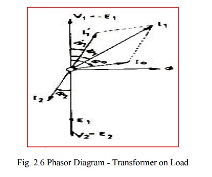
n o-load to full load. Vector diagram for an ideal transformer supplying
inductive load which is shown below.

In actual
practice, both of the primary and have got some ohmic resistance causing
voltage drops and copper losses in the windings. In actual practice, the total
flux created does not link both of the primary and secondary windings but is
divided into three components namely the main or mutual flux linking both of
the primary and secondary windings, primary leakage flux linking with primary
winding only and secondary leakage flux linking with secondary winding only.
The primary
leakage flux is produced by primary ampere-turns and is proportional to primary
current, number of primary turns being fixed. The primary leakage flux is in
phase with and produces self induced emf is in phase with and produces self
induced emf E given as 2f in the primary winding.
The self
induced emf divided by the primary current gives the reactance of primary and
is denoted by
E = 2fπ
Related Topics