Chapter: Electrical Engineering and Instrumentation : Transformer
Transformer - Electrical Engineering and Instrumentation
TRANSFORMER
Introduction
A transformer is a device that changes ac electric power at one voltage level to ac electric power at another voltage level through the action of a magnetic field.
There are two or more stationary electric circuits that are coupled magnetically.
It involves interchange of electric energy between two or more electric systems.
Transformers provide much needed capability of changing the voltage and current levels easily.
They are used to step-up generator voltage to an appropriate voltage level for power transfer.
Stepping down the transmission voltage at various levels for distribution and power utilization.
1. Transformer Classification
In terms of number of windings
Conventional transformer: two windings
Autotransformer: one winding
Others: more than two windings
In terms of number of phases
Single-phase transformer
Three-phase transformer
Depending on the voltage level at which the winding is operated
Step-up transformer: primary winding is a low voltage (LV) winding
Step-down transformer : primary winding is a high voltage (HV) winding
2. Primary and Secondary Windings
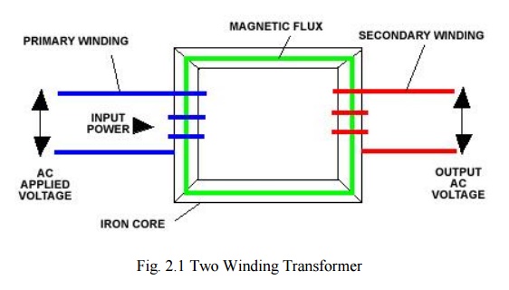
A two-winding transformer is shown below. It consists of two windings interlinked by a mutual magnetic field.
Primary winding –energized by connecting it to an input source.
Secondary winding –winding to which an electrical load is connected and from which outputenergy is drawn.

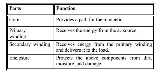
3. Functions of Transformer Parts

4. Principle of Operation
When current in the primary coil changes being alternating in nature, a changing magnetic field is produced
This changing magnetic field gets associated with the secondary through the soft iron core
Hence magnetic flux linked with the secondary coil changes.
Which induces e.m.f. in the secondary.
5. Ideal Transformer
An ideal transformer is a transformer which has no loses, i.e. it’s winding has no ohmic
resistance, no magnetic leakage, and therefore no I2 R and core loses.
However, it is impossible to realize such a transformer in practice.
Yet, the approximate characteristic of ideal transformer will be used in characterized the practical transformer.
For ideal transformer E1=V1 and E2= V2

Related Topics