Chapter: Protection and Switchgear : Protection of Feeders
Transformer Protection
TRANSFORMER PROTECTION
INTRODUCTION
• The power transformer is one of the most important links in a power transmission and distribution system.
• It is a highly reliable piece of equipment. This reliability depends on
• adequate design
• careful erection
• proper maintenance
• application of protection system.
PROTECTION EQUIPMENT INCLUDES
1. Surge diverters
2. Gas relay: It gives early warning of a slowly developing fault, permitting shutdown and repair before severe damage can occur.
3. Electrical relays.
• The choice of suitable protection is also governed by economic considerations.
Although this factor is not unique to power transformers, it is brought in prominence by the wide range of transformer ratings used( few KVA to several hundreds MVA)
• Only the simplest protection such as fuses can be justified for transformers of lower ratings.
• for large transformers best protection should be provided.
TYPES OF FAULTS AFFECTING POWER TRANSFORMER
· THROUGH FAULTS
a) Overload conditions.
b) External short-circuit conditions.
The transformer must be disconnected when such faults occur only after allowing a predetermined time during which other protective gears should have operated.
· INTERNAL FAULTS
The primary protection of a power transformer is intended for conditions which arises as a result of faults inside the protection zone.
1. Phase-to-earth fault or phase- to- phase fault on HV and LV external terminals
2. Phase-to-earth fault or phase-to- phase fault on HV and LV windings.
3. Interturn faults of HV and LV windings.
4. Earth fault on tertiary winding, or short circuit between turns of a tertiary windings.
5. So called „incipient‟ faults which are initially minor faults, causing gradually developing fault. These types of faults are not easily detectable at the winding terminals by unbalance current or voltage.
NATURE & EFFECT OF TRANSFRMER FAULTS
A faults on transformer winding is controlled in magnitude by
a) Source & neutral earthing impedance
b) Leakage reactance of the transformer
c) Position of the fault on the winding.
Following distinct cases are examined below (1) Star connected winding with neutral point earthed through an impedance
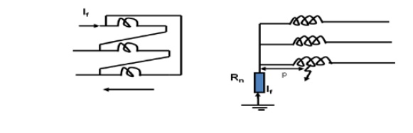
Earth fault on resistance earthed star winding
Transformer differential protection
Basic discussions related to the Merz-Price Scheme and its limitations which are taken care by the biased differential scheme, are omitted for repetition
Basic considerations
a. Transformation ratio
· The nominal currents in the primary and secondary sides of the transformer vary in inverse ratio to the corresponding voltages. This should be compensated for by using different transformation ratios for the CTs on the primary and secondary sides of the transformer.
b. Current Transformer Connections
· When a transformer is connected in star/delta, the secondary current has a phase shift of 300 relative to the primary
· This phase shift can be offset by suitable secondary CT connections
· The zero-sequence currents flowing on the star-side of the transformer will not produce current outside the delta on the other side. The zero sequence current must therefore be eliminated from the star-side by connecting the CTs in delta.
· • The CTs on delta side should be connected in star in order to give 300 phase shift.
· • When CTs are connected in delta, their secondary ratings must be reduced to 1/3 times the secondary ratings of the star-connected transformer, in order that the currents outside the delta may balance with the secondary currents of the star-connected CTs.
· • If transformers were connected in star/star, the CTs on both sides would need be connected in delta-delta.
c. Bias to cover tap-changing facility and CT mismatch
· If the transformer has the benefit of a tap changer, it is possible to vary its transformation ratio for voltage control.
· • The differential protection system should be able to cope with this variation.
· • This is because if the CTs are chosen to balance for the mean ratio of the power transformer, a variation in ratio from the mean will create an unbalance proportional to the ratio change. At maximum through fault current, the spill output produced by the small percentage unbalance may be substantial
· • Differential protection should be provided with a proportional bias of an amount which exceeds in effect the maximum ratio deviation. This stabilizes the protection under through fault conditions while still permitting the system to have good basic sensitivity.
d. Magnetization Inrush
· The magnetizing inrush produces a current flow into the primary winding that does not have any equivalent in the secondary winding. The net effect is thus similar to the situation when there is an internal fault on the transformer.
· Since the differential relay sees the magnetizing current as an internal fault, it is necessary to have some method of distinguishing between the magnetizing current and the fault current using one or all of the following methods.
· Using a differential relay with a suitable sensitivity to cope with the magnetizing current, usually obtained by a unit that introduces a time delay to cover the period of the initial inrush peak.
· • Using a harmonic-restraint unit, or a supervisory unit, in conjunction with a differential unit.
· • Inhibiting the differential relay during the energizing the transformer.
Compared to the differential protection used in generators, there are certain important points discussed below which must be taken care of while using such protection for the power transformers.
1. In a power transformer, the voltage rating of the two windings is different. The high voltage winding is low current winding while low voltage winding is high current winding. Thus there always exists difference in current on the primary and secondary sides of the power transformer. Hence if C.T.s of same ratio are used on two sides, then relay may get operated through there is no fault existing.
To compensate for this difficulty, the current ratios of C.T.s on each side are different. These ratios depend on the line currents of the power transformer and the connection of C.T.s. Due to the different turns ratio, the currents fed into the pilot wires from each end are same under normal conditions so that the relay remains inoperative. For example if K is the turns ratio of a power transformer then the ratio of C.T.s on low voltage side is made K times greater than that of C.T.s on high voltage side.
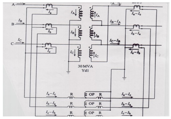
In case of power transformers, there is an inherent phase difference between the voltages induced in high voltage winding and low voltage winding. Due to this, there exists a phase difference between the line currents on primary and secondary sides of a power transformer. This introduces the phase difference between the C.T. secondary currents, on the two sides of a power transformer. Through the turns ratio of C.T.s are selected to compensate for turns ratio of transformer, a differential current may result due to the phase difference between the currents on two sides. Such a different current may operate the relay though there is no fault. Hence it is necessary to correct the phase difference. To compensate for this, the C.T. connections should be such that the resultant currents fed into the pilot wires from either sides are displaced in phase by an angle equal to the phase shift between the primary and secondary currents. To achieve this, secondaries of C.T.s on star connected side of a power transformer are connected in delta while the secondaries of C.T.s on delta connected side of a power transformer are connected in star.
Buchholz relay
All faults below the oil in transformer result in the localized heating & breakdown of the oil, some degree of arcing will always take place in a winding fault & the resulting decomposition of it will release gases such as hydrogen, carbon monoxide & hydrocarbons.
• When the fault is of a very minor type, such as hot joints gas is released slowly, but a major fault involving severe arcing causes rapid release of large volumes of gas as well as oil vapour.
• Such incipient faults of smaller or larger magnitudes can be detected by a gas actuated relay known as Bucholtz Relay.
The Bucholtz Relay is contained in a cast housing which is connected as shown below between the conservator tank and main tank of the transformer.
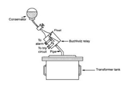
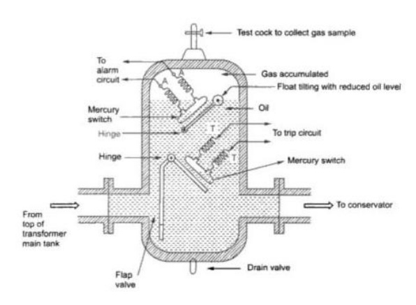
Under normal conditions, the Buchholz relay is full of oil. It consists of a cast housing containing a hinged hollow float. A mercury switch is attached to a float. The float being rotated in the upper part of the housing. Another hinged flap valve is located in the lower part which is directly in the path of the oil between tank and the conservator. Another mercury switch is attached to a flap valve. The float closes the alarm circuit while the lower flap valve closes the trip circuit in case of internal faults.
Operation
There are many types of internal faults such as insulation fault, core heating, bad switch contacts, faulty joints etc. which can occur. When the fault occurs the decomposition of oil in the main tank starts due to which the gases are generated. As mentioned earlier, major component of such gases is hydrogen. The hydrogen tries to rise up towards conservator but in its path it gets accumulated in the upper part of the Buchholz relay. Through passage of the gas is prevented by the flap valve.
When gas gets accumulated in the upper part of housing, the oil level inside the housing falls. Due to which the hollow float tilts and closes the contacts of the mercury switch attached to it. This completes the alarm circuit to sound an alarm. Due to this operator knows that there is some incipient fault in the transformer. The transformer is disconnected and the gas sample is tested. The testing results give the indication, what type of fault is started developing in the transformer.
Hence transformer can be disconnected before grows into a serious one. The alarm circuit does not immediately disconnect the transformer but gives only an indication to the operator. This is because sometimes bubbles in the oil circulating system may operate the alarm circuit even though actually there is no fault. However if a serious fault such as internal short circuit between phases, earth fault inside the tank etc. occurs then the considerable amount of gas gets generated. In that case, due to a fast reduction in the level of oil, the pressure in the tank increases. Due to this the oil rushes towards the conservator. While doing so it passes through the relay where flap valve is present. The flap valve gets deflected due to the rushing oil and operates the mercury switch, thereby energizing the trip circuit which opens the circuit breaker of transformer is totally disconnected from the supply. The connecting pipe between the tank and the conservator should be as straight as possible and should slope upwards conservator at a small angle from the horizontal. This angle should be around 100. For the economic considerations, Buchholz relays are not provided for the transformer having rating below 500 KVA.
Advantages
The various advantages of the Buchholz relay are,
1. Normally a protective relay does not indicate the appearance of the fault. It operates when fault occurs. But Buchholz relay gives an indication of the fault at very early stage, by anticipating the fault and operating the alarm circuit. Thus the transformer can be taken out of service before any type of serious damage occurs.
2. It is the simplest protection in case of transformers.
Limitations
The various limitation of the Buchholz relay are,
1. Can be used only for oil immersed transformers having conservator tanks.
2. Only faults below oil level are detected.
3. Setting of the mercury switches cannot be kept too sensitive otherwise the relay can operate due to bubbles, vibration, earthquakes mechanical shocks etc.
4. The relay is slow to operate having minimum operating time of 0.1 seconds and average time of 0.2 seconds.
Applications
The following types of transformer faults can be protected by the Buchholz relay and are indicated by alarm:
1. Local overheating
2. Entrance of air bubbles in oil
3. Core bolt insulation failure
4. Short circuited laminations
5. Loss of oil and reduction in oil level due to leakage
6. Bad and loose electrical contacts
7. Short circuit between phases
8. Winding short circuit
9. Bushing puncture
10. Winding earth fault.
Related Topics