Chapter: Protection and Switchgear : Protection of Feeders
Current Transformers(CT)s and Potential Transformer(PT)s and their applications in protection schemes
CTs and PTs and their applications in protection schemes
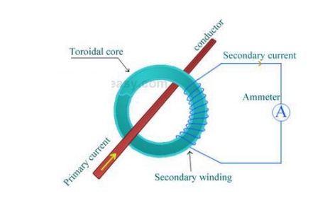
Current transformers are generally used to measure currents of high magnitude. These transformers step down the current to be measured, so that it can be measured with a normal range ammeter. A Current transformer has only one or very few number of primary turns. The primary winding may be just a conductor or a bus bar placed in a hollow core (as shown in the figure). The secondary winding has large number turns accurately wound for a specific turns ratio.

Thus the current transformer steps up (increases) the voltage while stepping down (lowering) the current. Now, the secondary current is measured with the help of an AC ammeter. The turns ratio of a transformer is NP / NS = IS / IP
· UPS systems
· Transfer switches
· Motor-generator sets
· Commercial sub-metering,
· CT 's in one package for 3-phase metering
· Accurate measuring for metering/WATT/VAR
· Current sensing, recording, monitoring & control
· Control panels and drives
· Standard CT used as measuring standard for comparison
· Winding temperature indicator (WTI) for power transformers
· Summation current transformers.
Potential Transformer (PT)
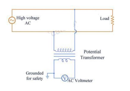
Potential transformers are also known as voltage transformers and they are basically step down transformers with extremely accurate turns ratio. Potential transformers step down the voltage of high magnitude to a lower voltage which can be measured with standard measuring instrument. These transformers have large number of primary turns and smaller number of secondary turns. A potential transformer is typically expressed in primary to secondary voltage ratio. For example, a 600:120 PT would mean the voltage across secondary is 120 volts when primary voltage is 600 volts.

Related Topics