Chapter: Protection and Switchgear : Protection of Feeders
Generator protection
Generator protection
INTRODUCTION
· The range of size of generators extends from a few hundred KVA to more than 500MVA
· Small and Medium sized sets may be directly connected to the distribution system
A larger unit is usually associated with an individual transformer, through which the set is coupled to the EHV transmission system. No switchgear is provided between the generator and transformer, which are treated as a unit.
Biased Differential scheme (Merz-Price Scheme) for protection of Generators.
This is most commonly used protection scheme for the alternator stator windings. The scheme is also called biased differential protection and percentage differential protection. The figure below shows a schematic arrangement of Merz-Price protection scheme for a star connected alternator.
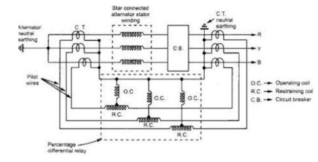
The differential relay gives protection against short circuit fault in the stator winding of a generator. When the neutral point of the windings is available then, the C.T.s may be connected in star on both the phase outgoing side and the neutral earth side, as shown in the above figure. But, if the neutral point is not available, then the phase side CTs are connected in a residual connection, so that it can be made suitable for comparing the current with the generator ground point CT secondary current. The restraining coils are energized from the secondary connection of C.T.s in each phase, through pilot wires. The operating coils are energized by the tappings from restraining coils and the C.T. neutral earthing connection.
The similar arrangement is used for the delta connected alternator stator winding, as shown below.
This scheme provides very fast protection to the stator winding against phase to phase faults and phase to ground faults. If the neutral is not grounded or grounded through resistance then additional sensitive earth fault relay should be provided. The advantages of this scheme are, 1. Very high speed operation with operating time of about 15 msec. 2. It allows low fault setting which ensures maximum protection of machine windings. 3. It ensures complete stability under most severe through and external faults. 4. It does not require current transformers with air gaps or special balancing features.
Earth fault protection of Generators
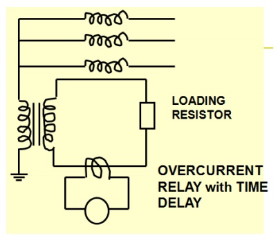
The neutral point of the generator is usually earthed, so as to facilitate the protection of the stator winding and associated system. Impedance is inserted in the earthing lead to limit the magnitude of the earth fault current. Generators which are directly connected to the transmission or distribution system are usually earthed through a resistance which will pass approximately rated current to a terminal earth fault. In case of generator-transformer unit, the generator winding and primary winding of a transformer can be treated as an isolated system that is not influenced by the earthing requirements of the transmission system. Modern practice is to use a large earthing transformer (5-100 KVA) – the secondary winding which is designed for 100-500V is loaded with a resistor of a value, which when referred through the transformer ratio, will pass a suitable fault current. The resistor is therefore of low value and can be of rugged construction. It is important that the earthing transformer never becomes saturated, otherwise a very undesirable condition of ferro resonance may occur.
Earth fault protection can be obtained by applying a relay to measure the transformer secondary current by connecting a voltage measuring relay in parallel with the load resistor
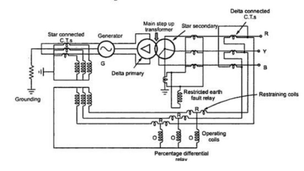
Generator and Transformer Unit Biased Differential Protection
In a high voltage transmission system, the bus bars are at very high voltages than the generators. The generators are directly connected to step up transformer to which it is connected, together from a generator transformer unit. The protection of such a unit is achieved by differential protection scheme using circulating current principle. While providing protection to such a unit, it is necessary to consider the phase shift and current transformation in the step up transformer. The figure in the following page, shows a biased differential protection scheme used for generator transformer unit. The zone of such a scheme includes the stator windings, the step up transformer and the intervening connections. The transformer is delta-star hence the current transformers on high voltage side are delta connected while those on generator side are star connected. This cancels the displacement between line currents introduced by the delta connected primary of the transformer. Where there is no fault, the secondary currents of the current transformer connected on generator side are equal to the currents in the pilot wires from the secondaries of the delta connected current transformers on the secondary of main transformer. When a fault occurs, the pilot wires carry the differential current to operate the percentage differential relay.
For the protection against the earth faults, an earth fault relays is put in the secondary winding of the main step up transformers as shown. In such a case, differential protection acts as a backup protection to the restricted earth fault protection. This overall differential protection scheme does not include unit transformer as a separate differential scheme is provided it.
PHASE FAULT
· Phase-phase faults clear of earth are less common. They may occur on the end portion of stator coils or in the slots if the winding involves two coil sides in the same slot. In the later case the fault will involve earth in a very short time.
· Phase fault current is not controlled by the method of earthing the neutral point.
INTERTURN FAULTS
· Interturn faults are also uncommon, but not unknown
· A greatest danger arising from failure to deal with interturn faults quickly is fire. A large portion of the insulation is inflammable
Negative sequence protection
The negative sequence component can be detected by the use of a filter network. Many negative sequence filter circuits have been evolved. One typical negative sequence filter circuit is as follows
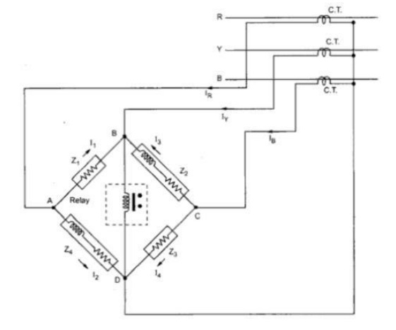
Basically it consists of a resistance bridge network as depicted in the first figure showing the circuit connection. The magnitudes of the impedances of all the branches of the network are equal. The impedances Z1 and Z3 are purely resistive while the impedances Z2 and Z4 are the combinations of resistance and reactance. The currents in the branches Z2 and Z4 lag by 60o from the currents in the branches Z1 and Z3. The vertical branch B-D basically consists of an over current element with inverse time characteristics having negligible impedance compared to the bridge impedances.
Related Topics