Chapter: Protection and Switchgear : Protection of Feeders
Over current and earth fault protection
Over current and earth fault protection
It is customary to have two elements of over current and one element of earth fault protection system in the most elementary form of protection of three phase feeders. Different types of feeders employ the over current protection along with the directional relay so that proper discrimination of an internal fault is possible. Some examples are illustrated below.
Application of directional relays to parallel feeders
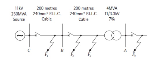
It may be seen from the below given parallel feeders that the relays placed at the load side of both the lines use directional element which respond to a direction away from the bus bars. Similarly, the relays placed at the source side do not require any directional element.
A similar concept of discrimination is also utilized in the below given ring main feeder and a feeder fed from both the sides. It can be observed that relays placed near the bus connecting the sources, don not have any directional feature, where as the rest of the buses, respond to a direction always away from the source. It is good practice to locate a fault any where among different sections of the feeders and check whether that particular section only is isolated without disrupting the power flow in other sections.
Pilot wire schemes for feeder protection
In differential protection scheme, the current entering at one end of the line and leaving from other end of the line is compared. The pilot wires are used to connect the relays. Under normal working condition, the two currents at both ends are equal and pilot wires do not carry any current, keeping relays inoperative. Under an internal fault condition, the two currents at both the ends are no longer same, this causes circulating current flow through pilot wires and makes the relay to trip. The various schemes used with this method of protection are, 1. Merz-Price Voltage Balance System 2. Translay Scheme
Merz-Price Voltage Balance System
The figure below shows Merz-Price voltage balance system used for the three phase feeders.
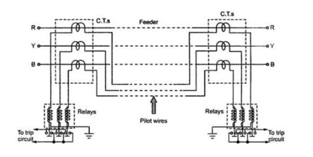
Under normal condition, current entering the line at one end is equal to current leaving from the other end. Therefore, equal and opposite voltages are induced in the secondaries of C.T.s. at the two ends resulting in no current flow, through the relay. Under fault condition, two currents at the two ends are different. Thus the secondary voltages of both the end C.T.s differ from each other. This circulates a circulating current through the pilot wires and the relays. Thus the relays trip the circuit breakers to isolate the faulty section.
The advantages of this method are as follows
1. It can be used for parallel as well as ring main system.
2. It provides instantaneous protection to ground faults.
The limitations of this method are as follows
1. The C.T.s used must match accurately.
2. The pilot wires must be healthy without discontinuity.
3. Economically not suitable as the cost is high due to long pilot wires.
4. Due to long pilot wires, capacitive effects adversely bias the operation of the relays.
5. The large voltage drop in the pilot wires requiring better insulation.
Translay Scheme
The translay relay is another type of differential relay. The arrangement is similar to overcurrent relay but the secondary winding is not closed on itself. Additionally copper ring or copper shading bands are provided on the central limb as shown in the figure below.
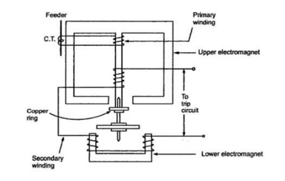
Role of copper ring:
Mainly relays may operate because of unbalance in the current transformers. The copper rings are so adjusted that the torque due to current induced in the copper ring due to primary winding of relay is restraining and do not allow the disc to rotate. It is adjusted just to neutralize the effect of unbalance existing between the current transformers. The copper rings also neutralize the effect of pilot capacitive currents. Though the feeder current is same at two ends, a capacitive current may flow in the pilots. This current leads the secondary voltage by 90o. The copper rings are adjusted such that no torque is exerted on the disc, due to such capacitive pilot currents. Therefore in this scheme the demerits of pilot relaying scheme is somewhat taken care of.
The advantages of this scheme are, 1. Only two pilot wires are required.
2. The cost is very low.
3. The current transformers with normal design can be employed.
4. The capacitive effects of pilot wire currents do not affect the operation of the relays.
Carrier Current unit protection system
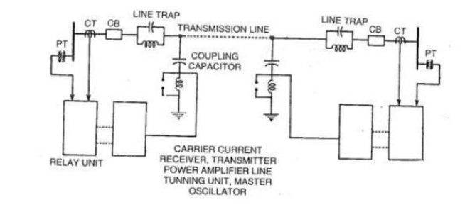
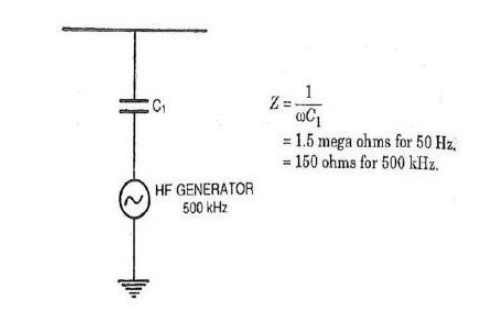
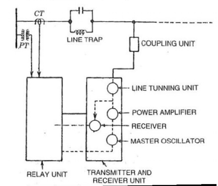
Schematic diagram of the carrier current scheme is shown below. Different basic components of the same are discussed below. The Coupling capacitor These coupling capacitors (CU) which offer low reactance to the higher frequency carrier signal and high reactance to the power frequency signal. Therefore, it filters out the low ( power) frequency and allows the high frequency carrier waves to the carrier current equipments. A low inductance is connected to the CU, to form a resonant circuit.
Wave Traps
The Wave traps ( also known as Line Trap) are inserted between the busbar and the connection of the CU. These traps are L and C elements connected in parallel, and they are tuned in such a manner that they offer low reactance to the power frequency signals and high reactance to the carrier waves. They ensure that neither of these different frequency signals get mixed up before being received at the bus bar. Both the CU and the Wave traps are protected from switching and lightening surges, with the help suitably designed Spark Gaps or Varistors. Frequency spacing Different frequencies are used in adjacent lines and the wave traps ensure that carrier signals of other lines do not enter a particular line section. Therefore, proper choice of frequency bands for different lines are adopted.
Transmitter Unit
In a Transmitter unit, the carrier frequency in the range of 50 to 500 KHz of constant magnitude is generated in the oscillator, which is fed to an amplifier. Amplification is required to overcome any loss in the coupling equipments, weather conditions, Tee connections in the lines of different size and length. The amplifier and the oscillators are constantly energized and a connection is made between the two with the help of a control unit.
The Receiver unit consists of an attenuator and a Band pass filter, which restricts the acceptance of any unwanted signals. The unit also has matching transformer to match the line impedance and that of the receiver unit.
Related Topics