Chapter: Electric Energy Generation and Utilisation and Conservation : Electric Drives and Traction
Track Equipment and Current Collecting System
Track Equipment and Current Collecting system
A. Electric Locomotive:
Construction of electric locomotive is described below
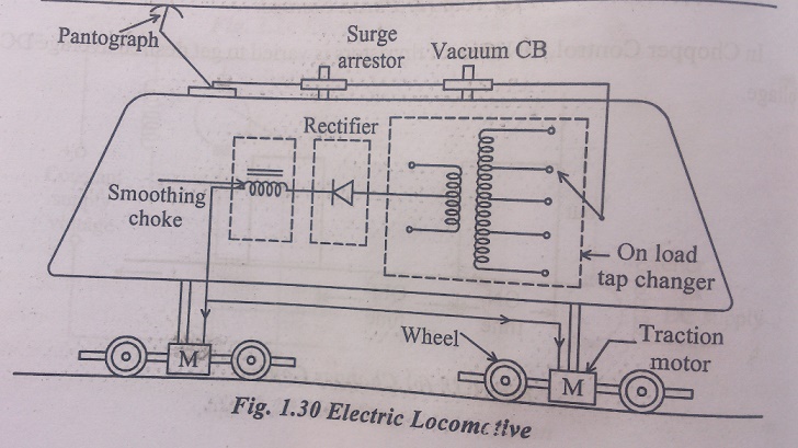
Electric locomotive consists of
1) Current collectors
2) Surge arrestor
3) Vacuum circuit Braker
4) On-load tap changer
5) Rectifier
6) Smoothing choke
7) Traction motor
8) ARNO converter
9) ARNO converter
10) Protective equipments
1) Current collectors
It is device which is used to current collection from overhead wire. It remains in sliding contact with overhead wire at all speeds. Structure is made of high tensile alloys steel tubing and can be raised or lowered using compressed air or springs.
2) Surge arrestor
It is used to bypass surges from OHE to ground.
3) Vacuum circuit Breaker
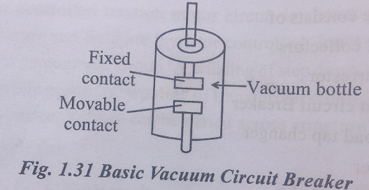
It is mounted on the rooftop of the locomotive. It consists of a vacuum bottle having a fixed and a movable contact separated by a small distance as shown in Fig .1.31. When CB is closed, the two constacts – fixed and movable contact touch each other inside the bottle and current from pantograph is conveyed to the tap changing transformer. When power supply need to be switched off, the CB is opened so that fixed and moving contacts inside the vacuum bottle separate thereby interrupting the circuit. The vacuum between fixed and moving constant acts as arc quenching medium. When contacts begin to separate, an arc is formed. This is quenched by the vacuum medium. The CB apart from normal switch on and off operation, also operates under some abnormal condition thereby protecting downstream equipments.
4) On-load tap changer
It is a transformer fitted with on-load lap changer. It is housed inside the locomotive cabin. 25 kV A.C power is stepped down to 1500 V by means of taps. Speed is controlled by on-load changer. The transformer winding is divided into 32 steps. With first step corresponding to 0 volts and 32 step corresponding to 1500V. The voltage output o transformer can be progressively increased to control speed. However, in thyristor controlled AC locomotives, there is no need or tap changers and rectifiers. Voltage is regulated by changing firing angle of thyristors.
5) Rectifier
It converts input AC voltage into DC output voltage. It provides full wave rectifier to DC series motor.
6) Smoothing choke
It removes ripples from rectifier DC output and feeds to DC traction motor.
7) Traction motor
It is DC series motor which provides motive power to wheels. Each axle of coach is driven by an individual traction motor.
8) ARNO converter
In order to keep size of locomotives small, it is necessary to keep size of transforms rectifier and traction motor small. This is possible by blowing air through them to keep temperature within limits. So number of blowers for traction motor transformer and rectifiers are provided. A compressor is also provided for supplying air required for braking of locomotive and or operation of pneumatically controlled equipment. (raising or lowering of pantograph) These auxiliary machines are providedwith 3ϕ AC motors.
9) ARNO converter
Supply fed to locomotive is single phase, 25 kV where as requirement for auxiliary machines is 3-phase 400 Volts. So a winding is provided in transformer to step down 25 kV to 400 V. This single phase 400 V is converted to 3-phase supply by a rotating machine called ARNO converter.
10) Protective equipments
In electric locomotives, protection is needed for operating personnel against contact with live circuit and safety of individual equipments against major damage due to a fault.
B. Current Collection System
The primary requirement of a collection system is that it should maintain a continuous contact with wire at all speed. There are mainly two current collection system namely current collection from conductor rail and current collection from Over Head Equipment (OHE).
B.1.Conductor Rail System
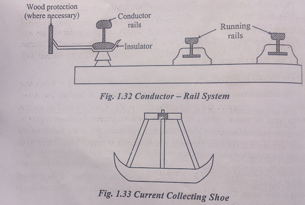
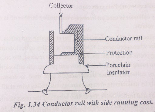
This conductor – rail system of supply has been used in many countries, or electric traction. In this system, the current is supplied to the electrically operated vehicle through one – rail conductor or through two – rail conductors.
· Depending on the positions of the contact surface, the conductor rail may be divided into three classes: Top, Bottom and Side.
· The top rail is adopted universally for 600V DC electrification.
· The side contact rail is used for 1200 V DC supply.
· The bottom contact rail has the advantage of being protected from show, sheet and ice.
B.2. Current Collection Gear for Over Head Equipment(OHE)
Main requirement of a collection gear is that it should under no circumstances leave the contact of OHE. Contact wire in all practical installations is never perfectly horizontal. It raises and falls depending upon the weight of the contact wire, and distance between droopers. Also contact wire comes very low under bridge and tunnels and rises high over public crossing. Depending upon the speed of the electric vehicle, collection gear has to raise and fall in order to maintain the contact with OHE.
The over head system used with D.C. tramways, trolley – buses and locomotives and also with AC. Locomotives. The track is used as the return conductor. The voltage in the overhead system is 600 V and above. The various material used for the overhead wire are hard drawn copper, cadmium-copper or silicon – bronze. Although of higher electrical resistance due to the higher tensile strength and wear resistance property, silicon-bronze is mostly used. Three types commonly used gear are:
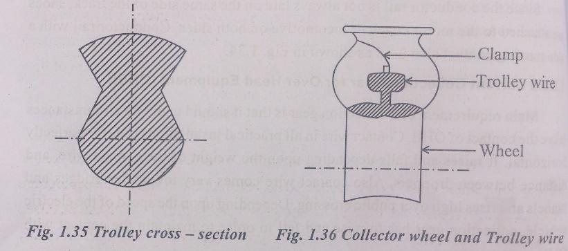
1. Trolley collector or pole collector
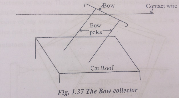
2. Bow collector and
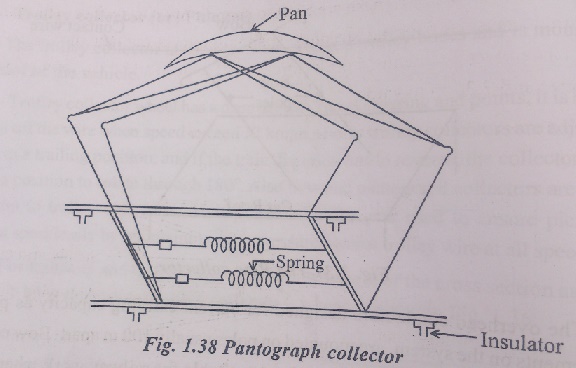
3. Pantograph collector
Trolley collector or pole collector
Bow collector and
Pantograph collector
Related Topics