Chapter: Mechanical : Gas Dynamics and Jet Propulsion : Jet Propulsion
The Turbojet Engine

The Turbojet Engine
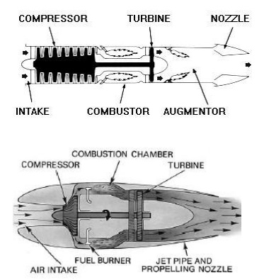
The turbojet engine consists of diffuser which shows
down the entrance air and thereby compresses it, a slows down the entrance air
and thereby compresses it, a simple open cycle gas turbine and an exist gas
into kinetic energy. The increased velocity, of air thereby produces thrust.
Figure 2 shows the basic arrangement of the
diffuser, compressor, combustion chamber, turbine and the exhaust nozzle of a
turbojet engine. Of the total pressure rise of air, a part is obtained by the
rain compression in the diffuser and rest in the compressor. The diffuser
converts kinetic energy of the air into pressure energy. In the ideal diffuser,
the air is diffused isentopically down to zero velocity. In the actual diffuser
the process is irreversible adiabatic and the air leaves the diffuser at a
velocity between 60 and 120 m/s

The centrifugal compressor gives a pressure ratio of
about 4:1 to 5:1 in a single stage and usually a double-sided rotor is used.
The turbojet using centrifugal compressor has a short and sturdy appearance.
The advantages of centrifugal compressor are high durability, ease of
manufacture and low cost and good operation under adverse conditions such as
icing and when sand and small foreign particles are inhaled in the inlet duct.
The primary disadvantage is the lack of straight-through airflow. Air leaves
compressor in radial direction and ducting with the attendant pressure losses
is necessary to change the direction. The axial flow is more efficient than the
centrifugal type and gives the turbojet a long slim, streamlined appearance.
The engine diameter is reduced which results in low aircraft drag. A multistage
axial flow compressor can develop a pressure ratio as high as 6:1 or more. The
air handled by it is more than that handled by a centrifugal compressor of the
same diameter.
A variation of the
axial compressor, the twin-spool (dual spool, split spool or coaxial)
compressor has two or more sections, each revolving at or near the optimum
speed for its pressure ratio and volume of air. A very high-pressure ratio of
about 9:1 to 13:1 is obtained. The use of high-pressure ratio gives very good
specific fuel consumption and is necessary for thrust ratings in the region of
50000 N or greater.
In
the combustion chamber heat is added to the compressed air nearly at constant
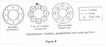
pressure. The three types being ‘can’, ‘annular’ and ‘can-annular’ (ref.fig.3).
In the can type individual burners, or cans, are mounted in a circle around the
engine axis with each one receiving air through its own cylindrical shroud. One
of the main disadvantages of can type burners is that they do not make the best
use of available space and this results in a large diameter engine. On the
other hand, the burners are individually removable for inspection and air-fuel
patterns are easier to control than in annular designs. The annular burner is
essentially a single chamber made of concentric cylinders mounted co-axially
about the engine axis. This arrangement makes more complete use of available
space, has low pressure loss, fits well with the axial compressor and turbine
and form a technical viewpoint has the highest efficiency, but has a
disadvantage in that structural problems may arise due to the large diameter,
thin-wall cylinder required with this type of chamber. The problem is more
severe for larger engines. There is also some disadvantage in that the entire
combustor must be removable from the engine for inspection and repairs. The
can- annular design also makes good use of available space, but employs a
number of individually replaceable cylindrical inner liners that receive air
through a common annular housing for good control of fuel and air flow
patterns. The can-annular arrangement has the added advantage of greater structural
stability and lower pressure loss than that of the can type.

The
heated air then expands through the turbine thereby increasing its velocity
while losing pressure. The turbine extracts enough energy to drive the
compressor and the necessary auxiliary equipments. Turbines of the impulse,
reaction and a combination of both types are used. In general, it may be stated
that those engines of relatively low thrust and simple design employ the
impulse type, while those of large thrust employ the reaction and combination
types.
The hot gas is then expended through the exit nozzle
and the energy of the hot gas is converted into as much kinetic energy as is
possible. This change in velocity of the air passing through the engine
multiplied by the mass flow of the air is the change of momentum, which
produces thrust. The nozzle can be a fixed jet or a variable area nozzle. The
variable area nozzle permits the turbojet to operate at maximum efficiency over
a wide range of power output. Clamshell, Finger or Iris, Centre plug with movable
shroud, annular ring, annular ring with movable shroud are the various types of
variable area nozzle for turbojet engines. The advantage of variable area
nozzle is the increased cost, weight and complexity of the exhaust system.
The needs and demands
being fulfilled by the turbojet engine are
Ø
Low specific weight – ¼ to ½ of the
reciprocating engine
Ø
Relative simplicity – no unbalanced
forces or reciprocating engine
Ø
Small frontal area, reduced air cooling
problem- less than ¼ th the frontal area of the
reciprocating engine giving a large
decrease in nacelle drag and consequently giving a greater available excess
thrust or power, particularly at high speeds.
Ø Not
restricted in power output - engines can be built with greatly increased power
output over that of the reciprocating engine without the accompanying
disadvantages.
Ø Higher
speeds can be obtained – not restricted by a propeller to speeds below 800
km/h.
Related Topics