Chapter: Electronic Circuits : Wave Shaping and Multivibrator Circuits
The RC Integrator
The RC Integrator
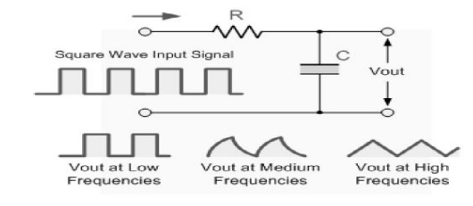
The Integrator
is basically a low pass filter circuit operating in the time domain that
converts a square wave "step" response input signal into a triangular
shaped waveform output as the capacitor charges and discharges.
A Triangular
waveform consists of alternate but equal, positive and negative ramps. As seen
below, if the RC time constant is long compared to the time period of the input
waveform the resultant output waveform will be triangular in shape and the
higher the input frequency the lower will be the output amplitude compared to
that of the input.

This then makes this type of circuit ideal for
converting one type of electronic signal to another for use in wave-generating
or wave-shaping circuits.
The Low
Pass Filter
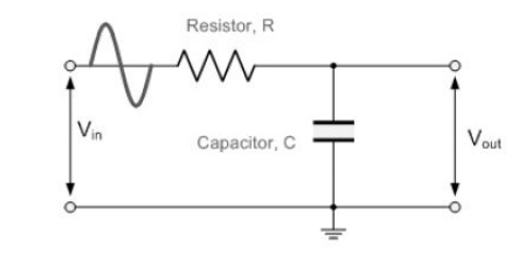
A simple passive Low Pass Filter or LPF, can be
easily made by connecting together in series a single Resistor with a single
Capacitor as shown below. In this type of filter arrangement the input signal
(Vin) is applied to the series combination (both the Resistor and Capacitor
together) but the output signal (Vout) is taken across the capacitor only.
This type of filter is known generally as a
"first-order filter" or "one-pole filter", why first-order
or single-pole, because it has only "one" reactive component in the
circuit, the capacitor.
Low Pass
Filter Circuit

The reactance of a capacitor varies inversely
with frequency, while the value of the resistor remains constant as the
frequency changes. At low frequencies the capacitive reactance, (Xc) of the
capacitor will be very large compared to the resistive value of the resistor, R
and as a result the voltage across the capacitor, Vc will also be large while
the voltage drop across the resistor, Vr will be much lower. At high
frequencies the reverse is true with Vc being small and Vr being large.
High
Pass Filters
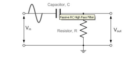
A High Pass Filter or HPF, is the exact
opposite to that of the Low Pass filter circuit, as now the two components have
been interchanged with the output signal (Vout) being taken from across the
resistor as shown.
Where the low pass filter only allowed signals
to pass below its cut-off frequency point, fc. The passive high pass filter
circuit as its name implies, only passes signals above the selected cut-off
point, fc eliminating any low frequency signals from the
waveform. Consider the circuit below.
The High
Pass Filter Circuit

In this circuit arrangement, the reactance of
the capacitor is very high at low frequencies so the capacitor acts like an
open circuit and blocks any input signals at Vin until the cut-off frequency
point (fc) is reached.
Above this cut-off frequency point the
reactance of the capacitor has reduced sufficiently as to now act more like a
short circuit allowing all of the input signal to pass directly to the output
as shown below in the High Pass Frequency Response Curve.
RC
Differentiator
Up until now the input waveform to the filter
has been assumed to be sinusoidal or that of a sine wave consisting of a
fundamental signal and some harmonics operating in the frequency domain giving
us a frequency domain response for the filter.
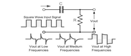
However, if we feed the High Pass Filter with a Square
Wave signal operating in the time domain giving an impulse or step response
input, the output waveform will consist of short duration pulse or spikes as
shown.

Each cycle of the square wave input waveform
produces two spikes at the output, one positive and one negative and whose
amplitude is equal to that of the input. The rate of decay of the spikes
depends upon the time constant, (RC) value of both components, (t = R x C) and
the value of the input frequency. The output pulses resemble more and more the
shape of the input signal as the frequency increases
Related Topics