Chapter: Electronic Circuits : Wave Shaping and Multivibrator Circuits
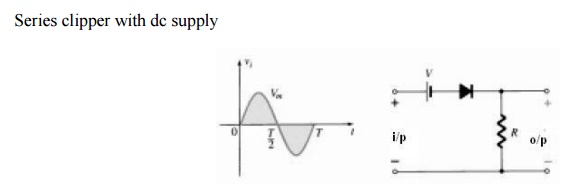
Series clipper
Clippers
Series clipper
The response of the series configuration to a
variety of alternating waveforms is provided although first introduced as a
half-wave rectifier (for sinusoidal waveforms); there are no boundaries on the
type of signals that can be applied to a clipper. The addition of a dc supply
can have a pronounced effect on the output of a clipper. Our initial discussion
will be limited to ideal diodes, with the effect of VT reserved for a
concluding example.
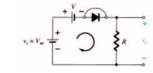
Circuit diagram:
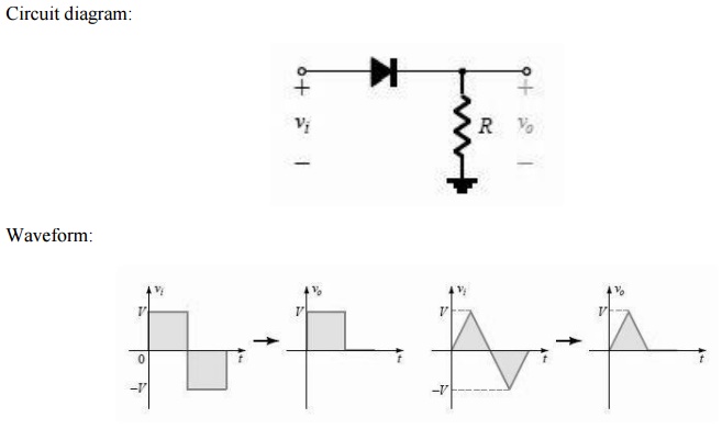
There is no general procedure for analyzing
networks such as the type in Fig but there are a few thoughts to keep in mind
as you work toward a solution. Make a mental sketch of the response of the
network based on the direction of the diode and the applied voltage levels. For
the network, the direction of the diode suggests that the signal must be
positive to turn it on. The dc supply further requires that the voltage be greater
than V volts to turn the diode on.
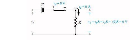
The negative region of the input signal is
―pressuring the diode into the ―off state, supported further by the dc supply.
In general, therefore, we can be quite sure that the diode is an open circuit
(―off
state) for the negative region of the input
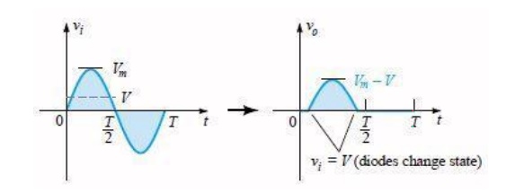
signal. Determine the applied voltage (transition voltage) that will cause a
change in state for the diode: For an input voltage greater than V volts the
diode is in the short-circuit state, while for input voltages less than V volts
it is in the open-circuit or ―off state.
Determining the transition level for the
circuit
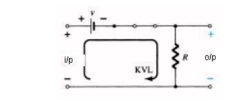
Be continually aware of the defined terminals
and polarity of Vo. When the diode is in the short-circuit state, such as shown
in Fig. , the output voltage Vo can be determined by applying
Kirchhoff‘s
voltage law in the clockwise direction Vi
– V – Vo (CW direction)
It can be helpful to sketch the input signal
above the output and determine the output at instantaneous values of the input:
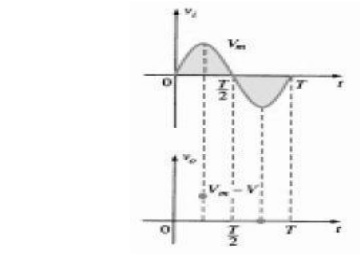
It is then possible that the output voltage can
be sketched from the resulting data points of as demonstrated. Keep in mind
that at an instantaneous value of vi the input can be treated as a dc supply of
that value and the corresponding dc value (the instantaneous value) of the
output determined. For instance, at Vi = Vm for the
network, the network to be analyzed appears. For Vm > V the diode
is in the short-circuit state and Vo = Vm - V.
Determining Levels Of Vo
Determining Vo When Vi =
Vm
At the Vi = Vm diodes
change state; at Vi = – Vm, Vo =0 V; and the
complete curve for Vo can be sketched.
Related Topics