Chapter: Civil : Principles of Solid Mechanics : Strategies for Elastic Analysis and Design
The Deviatoric Field and Photoelasticity
The Deviatoric
Field and Photoelasticity
The isotropic component
of the stress or strain field is therefore a scalar poten-tial function. That
is to say, the distance to the center of Mohr's Circle is a Laplacian or
Poisson field at every point in the structure. This field can be determined
analytically or experimentally in two dimensions by plotting a flow net,
assuming, as is seldom the case, that either the mean stress or its nor-mal
derivative is known around a closed boundary and body forces are con-stant or
zero.
The deviatoric
component of the stress tensor is more complicated in that vector fields are
involved rather than a simple scalar field. In three dimen-sions, the
deviatoric tensor involves three magnitudes, Si, (principal
values) and associated angles, ![]() i,
(orientation to the reference frame) and can,
i,
(orientation to the reference frame) and can,
![]()
therefore, be thought
of as three vectors, Si, describing the size and aspect
ratios of the Mohr's Circles.
In the planar care,
there is just one deviatoric vector, q , of magnitude ![]() max
=
max
= ![]() 13
=
13
= ![]() q
in the orientation 2
q
in the orientation 2![]() on Mohr's Circle. Thus
the deviatoric field is a vec-tor field expressing the two pieces of
information, magnitude and direction, at each point in the structure as they
flow from one boundary to another in accor-dance with the field equations.
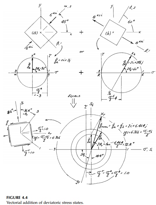
Figure 4.4 illustrates this vector property of the deviatoric stress at a point
by showing, for a specific example, how two states of stress (or strain) at a
point can be added together by adding the isotropic mean stresses algebraically
and the deviatoric vectors by the parallelogram rule.*
on Mohr's Circle. Thus
the deviatoric field is a vec-tor field expressing the two pieces of
information, magnitude and direction, at each point in the structure as they
flow from one boundary to another in accor-dance with the field equations.
Figure 4.4 illustrates this vector property of the deviatoric stress at a point
by showing, for a specific example, how two states of stress (or strain) at a
point can be added together by adding the isotropic mean stresses algebraically
and the deviatoric vectors by the parallelogram rule.*
![]()
Photoelasticity is a
beautiful experimental method of discovering and dis-playing this deviatoric
vector field with photographs. Like Moirť for dis-placements and interferometry
for the isotropic stress, photoelasticity is a full-field method and is much
easier, accurate, and more versatile. Two sets

of interference fringes
are observed when plane, polarized light is transmit-ted through a stressed
sheet (a model) of almost any transparent material in a crossed polariscope.
One of these sets is the isochromatic fringe pattern given by the fundamental
relationship or stress-optic law:

where the stresses are
in the plane of the model, t is the thickness of the model, N are
either integer, 0, 1, 2 ... or half-order (1/2, 3/2, 5/2...) depending on
whether the polariscope is crossed or aligned, and f is the stress-optic
fringe coefficient.
This fringe coefficient, in turn, is a property of the transparent material
being used for the model and the wave length, ![]() ,
of the transmitted light used to illuminate it.* Thus in white light, the
colors are extinguished in order giving a beautiful spectrum effect, which led
Maxwell to name these fringes isochromatics. For accurate experimental
analysis, monochromatic light or filters on the camera are used to give clearly
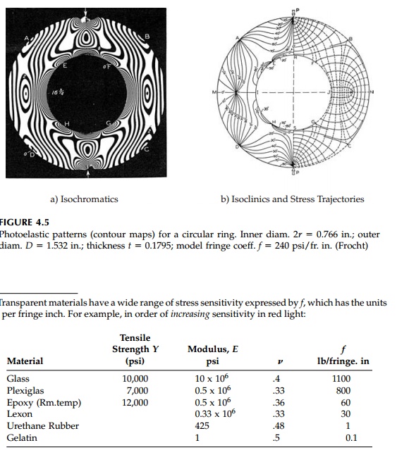
defined black lines on the photograph. An example of a diametrically loaded
thick ring is shown in Figure 4.5a. Thus in one photograph, a complete contour
map of the magni-tude of the in-plane deviatoric stress tensor field, S
or
,
of the transmitted light used to illuminate it.* Thus in white light, the
colors are extinguished in order giving a beautiful spectrum effect, which led
Maxwell to name these fringes isochromatics. For accurate experimental
analysis, monochromatic light or filters on the camera are used to give clearly
defined black lines on the photograph. An example of a diametrically loaded
thick ring is shown in Figure 4.5a. Thus in one photograph, a complete contour
map of the magni-tude of the in-plane deviatoric stress tensor field, S
or ![]() max
is determined and easily visualized.
max
is determined and easily visualized.
Isoclinic fringes are,
as the name implies, contour lines of equal orienta-tion of the principal
stresses to the Cartesian axes of the crossed polarizing plates (usually
horizontal and vertical). Isoclinics are black in white light
FIGURE
4.5

and can therefore be
differentiated from the colored isochromatics.* From the isoclinics,
stress-trajectories or paths of the principal stresses or maxi-mum shears can
easily be constructed graphically. Observed isoclinics and the principal stress
trajectories for a diametrically loaded thick ring are shown in Figure 4.5b.
Not only does
photoelasticity directly determine the complete deviatoric vector field, it
provides boundary conditions for the isotropic field. Since on a boundary one
principal stress is known (zero if unloaded), the other can be computed from
the isochromatic value for ![]() 1
=
1
= ![]() 2.
The flow-net for the har-monic mean stress and its conjugate can then be drawn
or calculated by computer without ambiguity and the entire stress field
determined. Even three-dimensional solutions are possible with photoelastic
analysis of slices from a stress-frozen model.
2.
The flow-net for the har-monic mean stress and its conjugate can then be drawn
or calculated by computer without ambiguity and the entire stress field
determined. Even three-dimensional solutions are possible with photoelastic
analysis of slices from a stress-frozen model.
Related Topics