Chapter: Electrical machines : Synchronous Motors
Synchronous Motors: Construction, Operating Principle, Equivalent Circuit
SYNCHRONOUS MOTORS
It may be recalled that a D.C. generator can be run as a D.C. motor. In same way, an alternator may operate as a motor by connecting its armature winding to a 3-phase supply. It is then called a synchronous motor. As the name implies, a synchronous motor runs at synchronous speed (Ns = 120f/P) i.e., in synchronism with the revolving field produced by the 3-phase supply. The speed of rotation is, therefore, tied to the frequency of the source. Since the frequency is fixed, the motor speed stays constant irrespective of the load or voltage of 3- phase supply. However, synchronous motors are not used so much because they run at constant speed (i.e., synchronous speed) but it found very useful applications because they possess other unique electrical properties.
General Physical Concept
Let assume that the armature winding (laid out in the stator) of a 3-phase synchronous machine is connected to a suitable balanced 3-phase source and the field winding to a D.C source of rated voltage. The current flowing through the field coils will set up stationary magnetic poles of alternate North and South. On the other hand, the 3-phase currents flowing in the armature winding produce a rotating magnetic field rotating at synchronous speed. In other words there will be moving North and South poles established in the stator due to the 3-phase currents i.e at any location in the stator there will be a North pole at some instant of time and it will become a South pole after a time period corresponding to half a cycle. (after a time = 1/2f, where f = frequency of the supply). Assume that the stationary South pole in the rotor is aligned with the North pole in the stator moving in clockwise direction at a particular instant of time, as shown in Figure below. These two poles get attracted and try to maintain this alignment (as per Lenz's law) and hence the rotor pole tries to follow the stator pole as the conditions are suitable for the production of torque in the clockwise direction. However, the rotor cannot move instantaneously due to its mechanical inertia, and so it needs some time to move. In the meantime, the stator pole would quickly (a time duration corresponding to half a cycle) change its polarity and becomes a South pole. So the force of attraction will no longer be present and instead the like poles experience a force of repulsion as shown in Figs. In other words, the conditions are now suitable for the production of torque in the anticlockwise direction. Even this condition will not last longer as the stator pole would again change to North pole after a time of 1/2f. Thus the rotor will experience an alternating force which tries to move it clockwise and anticlockwise at twice the frequency of the supply, i.e. at intervals corresponding to 1/2f seconds. As this duration is quite small compared to the mechanical time constant of the rotor, the rotor cannot respond and move in any direction. The rotor continues to be stationary only.
On the contrary if the rotor is brought to near synchronous speed by some external device say a small motor mounted on the same shaft as that of the rotor, the rotor poles get locked to the unlike poles in the stator and the rotor continues to run at the synchronous speed even if the supply to the motor is disconnected. Thus the synchronous rotor cannot start rotating on its own when the rotor and stator are supplied with rated voltage and frequency and hence the synchronous motor has no starting torque. So, some special provision has to be made either inside the machine or outside of the machine so that the rotor is brought to near about its synchronous speed. At that time, if the armature is supplied with electrical power, the rotor can pull into step and continue to run at its synchronous speed.
Construction
A synchronous motor is a machine that operates at synchronous speed and converts electrical energy into mechanical energy. It is fundamentally an alternator operated as a motor. Like an alternator, a synchronous motor has the following two parts:
(i) a stator which houses 3-phase armature winding in the slots of the stator core and receives power from a 3-phase supply [See (Fig: )].
(ii) a rotor that has a set of salient poles excited by direct current to form alternate N and S poles. The exciting coils are connected in series to two slip rings and direct current is fed into the winding from an external exciter mounted on the rotor shaft. The stator is wound for the same number of poles as the rotor poles. As in the case of an induction motor, the number of poles determines the synchronous
speed of the motor,
Ns = 120f/P
Where,
f = frequency of supply in Hz P = number of poles
An important drawback of a synchronous motor is that it is not self-starting and auxiliary means have to be used for starting it.
Operating Principle
The fact that a synchronous motor has no starting torque can be easily explained.
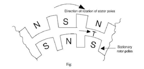
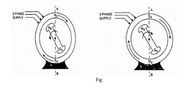
(i) Consider a 3-phase synchronous motor having two rotor poles NR and SR. Then the stator will also be wound for two poles NS and SS. The motor has direct voltage applied to the rotor winding and a 3-phase voltage applied to the stator winding. The stator winding produces a rotating field which revolves round the stator at synchronous speed Ns (= 120 f/P). The direct (or zero frequency) current sets up a two-pole field which is stationary so long as the rotor is not turning. Thus, we have a situation in which there exists a pair of revolving armature poles (i.e., NS - SS) and a pair of stationary rotor poles (i.e., NR - SR).
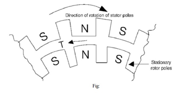
(ii) Suppose at any instant, the stator poles are at positions A and B as shown in Fig: It is clear that poles NS and NR repel each other and so do the poles SS and SR. Therefore, the rotor tends to move in the anticlockwise direction. After a period of half-cycle (or ½ f = 1/100 second), the polarities of the stator poles are reversed but the polarities of the rotor poles remain the same as shown in Fig: Now SS and NR attract each other and so do NS and SR. Therefore, the rotor tends to move in the clockwise direction. Since the stator poles change their polarities rapidly, they tend to pull the rotor first in one direction and then after a period of half-cycle in the other. Due to high inertia of the rotor, the motor fails to start. Hence, a synchronous motor has no self- starting torque i.e., a synchronous motor cannot start by itself.
Equivalent Circuit
Unlike the induction motor, the synchronous motor is connected to two electrical systems; a d.c. source at the rotor terminals and an a.c. system at the stator terminals.
1. Under normal conditions of synchronous motor operation, no voltage is induced in the rotor by the stator field because the rotor winding is rotating at the same speed as the stator field. Only the impressed direct current is present in the rotor winding and ohmic resistance of this winding is the only opposition to it as shown in Fig: (i).
2. In the stator winding, two effects are to be considered, the effect of stator field on the stator winding and the effect of the rotor field cutting the stator conductors at synchronous speed.
(i) The effect of stator field on the stator (or armature) conductors is accounted for by including an inductive reactance in the armature winding. This is called synchronous reactance Xs. A resistance Ra must be considered to be in series with this reactance to account for the copper losses in the stator or armature winding as shown in Fig: (i). This resistance combines with synchronous reactance and gives the synchronous impedance of the machine.
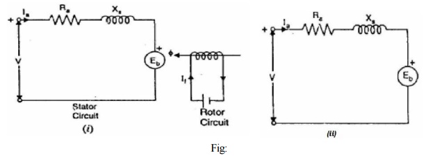
(ii) The second effect is that a voltage is generated in the stator winding by the synchronously-revolving field of the rotor as shown in Fig: 2.23 (i). This generated e.m.f. Eb is known as back e.m.f. and opposes the stator voltage V. The magnitude of Eb depends upon rotor speed and rotor flux ф per pole. Since rotor speed is constant; the value of Eb depends upon the rotor flux per pole i.e. exciting rotor current If.
Fig: 2.23 (i) shows the schematic diagram for one phase of a star-connected synchronous motor while Fig: 2.23 (ii) shows its equivalent circuit. Referring to the equivalent circuit in Fig: 2.23 (ii).
Net voltage/phase in stator winding is
Er = V - Eb phasor difference
Armature current/phase,
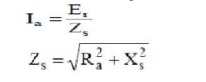
This equivalent circuit helps considerably in understanding the operation of a synchronous motor. A synchronous motor is said to be normally excited if the field excitation is such that Eb = V. If the field excitation is such that Eb < V, the motor is said to be under-excited. The motor is said to be over-excited if the field excitation is such that Eb > V. As we shall see, for both normal and under excitation, the motor has lagging power factor. However, for over-excitation, the motor has leading power factor.
Related Topics