Chapter: Digital Logic Circuits : Synchronous Sequential Circuits
Summary of the Types of Flip flop Behaviour
Summary of the Types of Flip-flop Behaviour
Since memory elements in sequential circuits are usually flip-flops, it is worth summarising the behaviour of various flip-flop types before proceeding further.
All flip-flops can be divided into four basic types: SR, JK, D and T. They differ in the number of inputs and in the response invoked by different value of input signals. The four types of flip-flops are defined in Table 1.
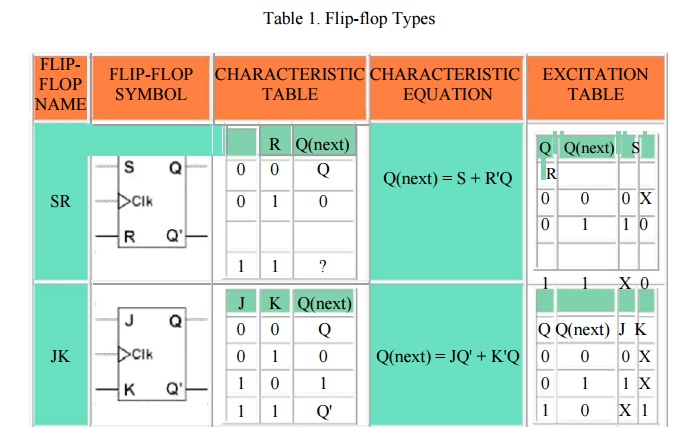
Each of these flip-flops can be uniquely described by its graphical symbol, its characteristic table, its characteristic equation or excitation table. All flip-flops have output signals Q and Q'.
The characteristic table in the third column of Table 1 defines the state of each flip-flop as a function of its inputs and previous state. Q refers to the present state and Q(next) refers to the next state after the occurrence of the clock pulse. The characteristic table for the RS flip-flop shows that the next state is equal to the present state when both inputs S and R are equal to 0. When R=1, the next clock pulse clears the flip-flop. When S=1, the flip-flop output Q is set to 1. The equation mark (?) for the next state when S and R are both equal to 1 designates an indeterminate next state.
The characteristic table for the JK flip-flop is the same as that of the RS when J and K are replaced by S and R respectively, except for the indeterminate case. When both J and K are equal to 1, the next state is equal to the complement of the present state, that is, Q(next) = Q'.
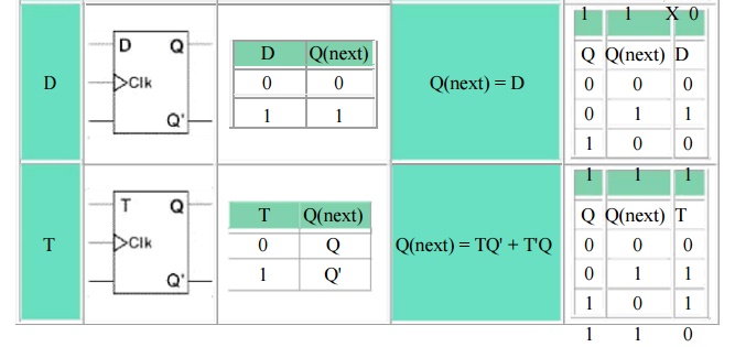
The next state of the D flip-flop is completely dependent on the input D and independent of the present state.
The next state for the T flip-flop is the same as the present state Q if T=0 and complemented if T=1.
The characteristic table is useful during the analysis of sequential circuits when the value of flip-flop inputs are known and we want to find the value of the flip-flop output Q after the rising edge of the clock signal. As with any other truth table, we can use the map method to derive the characteristic equation for each flip-flop, which are shown in the third column of Table 1.
During the design process we usually know the transition from present state to the next state and wish to find the flip-flop input conditions that will cause the required transition. For this reason we will need a table that lists the required inputs for a given change of state. Such a list is called the excitation table, which is shown in the fourth column of Table 1. There are four possible transitions from present state to the next state. The required input conditions are derived from the information available in the characteristic table. The symbol X in the table represents a "don't care" condition, that is, it does not matter whether the input is 1 or 0.
State Tables and State Diagrams
We have examined a general model for sequential circuits. In this model the effect of all previous inputs on the outputs is represented by a state of the circuit. Thus, the output of the circuit at any time depends upon its current state and the input. These also determine the next state of the circuit. The relationship that exists among the inputs, outputs, present states and next states can be specified by either the state table or the state diagram.
State Table
The state table representation of a sequential circuit consists of three sections labelled present state, next state and output. The present state designates the state of flip-flops before the occurrence of a clock pulse. The next state shows the states of flip-flops after the clock pulse, and the output section lists the value of the output variables during the present state.
State Diagram
In addition to graphical symbols, tables or equations, flip-flops can also be represented graphically by a state diagram. In this diagram, a state is represented by a circle, and the transition between states is indicated by directed lines (or arcs) connecting the circles. An example of a state diagram is shown in Figure 3 below.
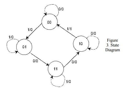
The binary number inside each circle identifies the state the circle represents. The directed lines are labelled with two binary numbers separated by a slash (/). The input value that causes the state transition is labelled first. The number after the slash symbol / gives the value of the output. For example, the directed line from state 00 to 01 is labelled 1/0, meaning that, if the sequential circuit is in a present state and the input is 1, then the next state is 01 and the output is 0. If it is in a present state 00 and the input is 0, it will remain in that state. A directed line connecting a circle with itself indicates that no change of state occurs. The state diagram provides exactly the same information as the state table and is obtained directly from the state table.
Example: This example is taken from P. K. Lala, Practical Digital Logic Design and Testing, Prentice Hall, 1996, p.155.
Consider a sequential circuit shown in Figure 4. It has one input x, one output Z and two state variables Q1Q2 (thus having four possible present states 00, 01, 10, 11).
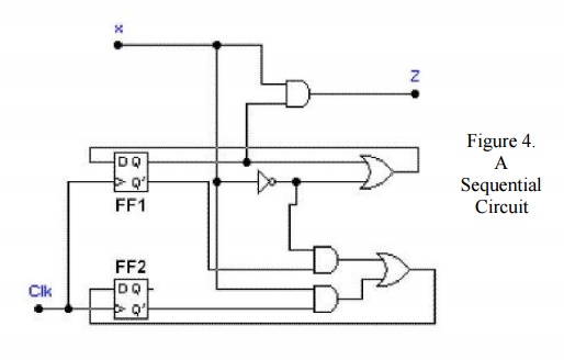
The behaviour of the circuit is determined by the following Boolean expressions:
Z = x*Q1
D1 = x' + Q1
D2 = x*Q2' + x'*Q1'
These equations can be used to form the state table. Suppose the present state (i.e. Q1Q2) = 00 and input x = 0. Under these conditions, we get Z = 0, D1 = 1, and D2 = 1. Thus the next state of the circuit D1D2 = 11, and this will be the present state after the clock pulse has been applied. The output of the circuit corresponding to the present state Q1Q2 = 00 and x = 1 is Z = 0. This data is entered into the state table as shown in Table 2.
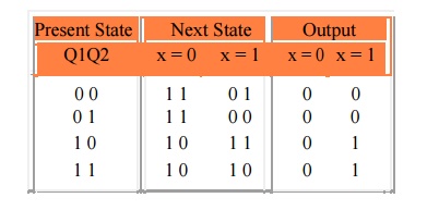
Table 2. State table for the sequential circuit in Figure 4.
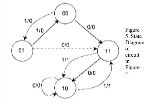
The state diagram for the sequential circuit in Figure 4 is shown in Figure 5.
State Diagrams of Various Flip-flops
Table 3 shows the state diagrams of the four types of flip-flops.
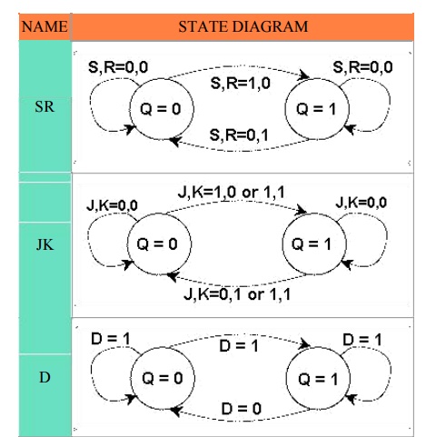
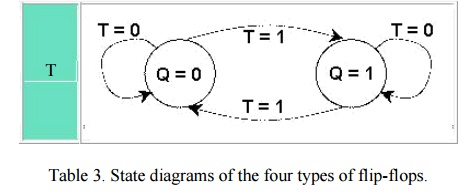
You can see from the table that all four flip-flops have the same number of states and transitions. Each flip-flop is in the set state when Q=1 and in the reset state when Q=0. Also, each flip-flop can move from one state to another, or it can re-enter the same state. The only difference between the four types lies in the values of input signals that cause these transitions.
A state diagram is a very convenient way to visualise the operation of a flip-flop or even of large sequential components.
Related Topics