Chapter: Digital Signal Processing : IIR Filter Design
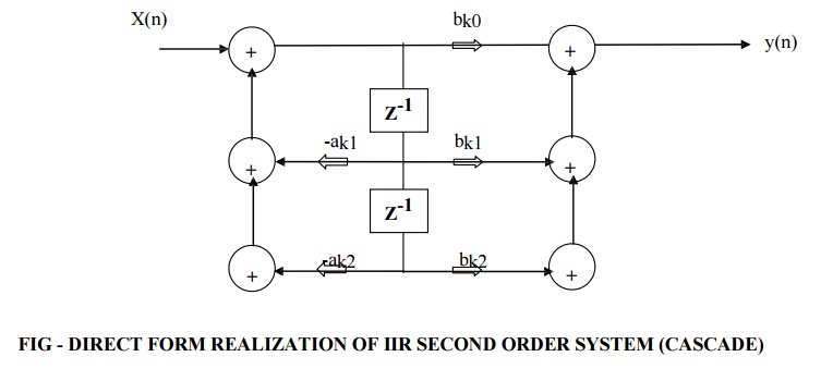
Structures For IIR Systems
STRUCTURES FOR IIR SYSTEMS
IIR
Systems are represented in four different ways
2. Cascade Form Structure
3. Parallel Form Structure
4. Lattice and Lattice-Ladder structure.
1.
DIRECT FORM STRUCTURE FOR IIR SYSTEMS
IIR
systems can be described by a generalized equations as
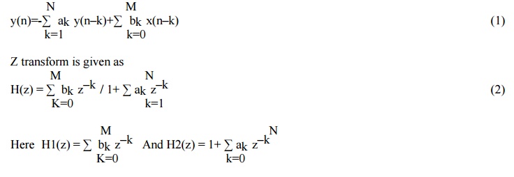
Overall
IIR system can be realized as cascade of two function H1(z) and H2(z). Here
H1(z) represents zeros of H(z) and H2(z) represents all poles of H(z).
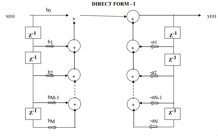
FIG - DIRECT FORM I REALIZATION OF IIR SYSTEM
1.
Direct form I realization of H(z) can be obtained
by cascading the realization of H1(z) which is all zero system first and then
H2(z) which is all pole system.
2. There are
M+N-1 unit delay blocks. One unit delay block requires one memory location.
Hence direct form structure requires M+N-1 memory locations.
3.
Direct Form I realization requires M+N+1 number of
multiplications and M+N number of additions and M+N+1 number of memory
locations.
DIRECT FORM - II
1. Direct form realization of H(z) can be obtained
by cascading the realization of H1(z) which is all pole system and H2(z) which
is all zero system.
2. Two delay elements of all pole
and all zero system can be merged into single delay element.
3. Direct Form II structure has
reduced memory requirement compared to Direct form I structure. Hence it is
called canonic form.
4. The direct form II requires
same number of multiplications(M+N+1) and additions (M+N) as that of direct
form I.
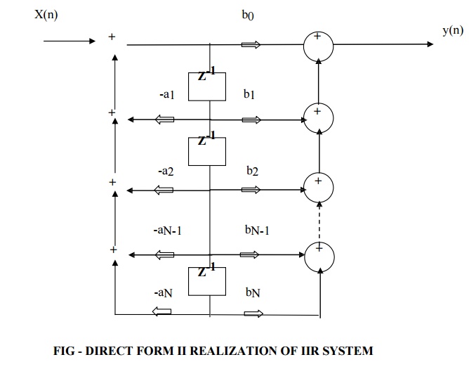
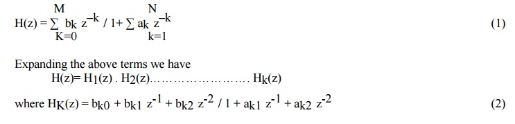
CASCADE FORM STRUCTURE FOR IIR SYSTEMS
H= H1(z)
. H2(z)……………………. Hk(z) (1)
H=
Y1(z)/X1(z). Y2(z)/X2(z). ……………Yk(z)/Xk(z) (2)
Each
H1(z), H2(z)… etc is a second order section and it is realized by the direct
form as shown in below figure.
System
function for IIR systems
Thus
Direct form of second order IIR system is shown as
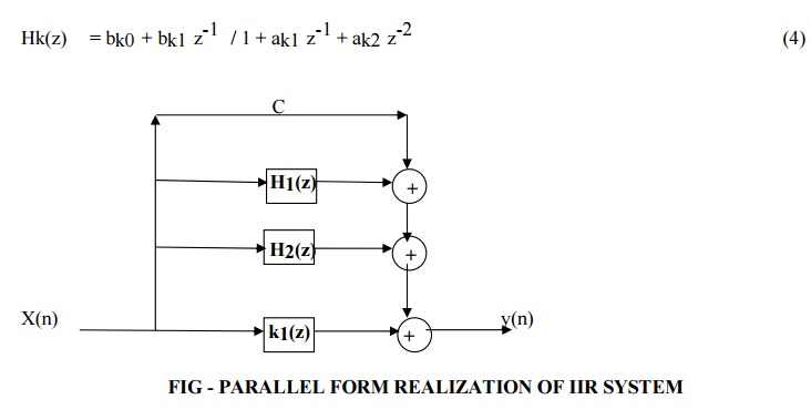
PARALLEL FORM STRUCTURE FOR IIR SYSTEMS
System
function for IIR systems is given as
The above
system function can be expanded in partial fraction as follows
H(z) = C + H1(z) + H2(z)…………………….+ Hk(z) (3)
Where C
is constant and Hk(z) is given as
IIR FILTER DESIGN
BILINEAR TRANSFORMATION
BUTTERWORTH APPROXIMATION
IIR FILTER DESIGN - IMPULSE INVARIANCE METHOD
Impulse
Invariance Method is simplest method used for designing IIR Filters. Important
Features of this Method are
1. In
impulse variance method, Analog filters are converted into digital filter just
by replacing unit sample response of the digital filter by the sampled version
of impulse response of analog filter. Sampled signal is obtained by putting
t=nT hence
h(n) =
ha(nT) n=0,1,2.
………….
where
h(n) is the unit sample response of digital filter and T is sampling interval.
2. But
the main disadvantage of this method is that it does not correspond to simple
algebraic mapping of S plane to the Z plane. Thus the mapping from analog frequency to digital frequency is many
to one. The segments
(2k-1)∏/T
≤ Ω ≤ (2k+1) ∏/T of j Ω axis are all mapped on the unit circle ∏≤ω≤∏. This
takes place because of sampling.
3. Frequency
aliasing is second disadvantage in this method. Because of frequency aliasing,
the frequency response of the resulting digital filter will not be identical to
the original analog frequency response.
4. Because
of these factors, its application is limited to design low frequency filters
like LPF or a limited class of band pass filters.
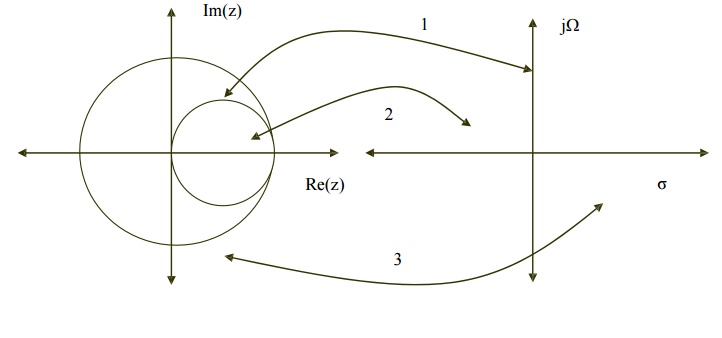
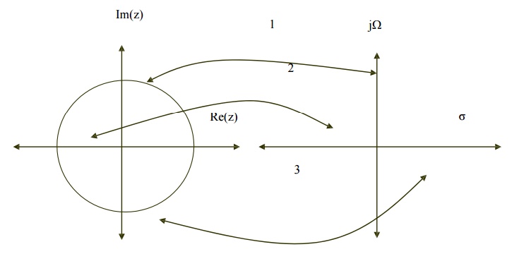
RELATIONSHIP BETWEEN Z PLANE AND S PLANE
Z is
represented as rejω in polar form and relationship between Z plane
and S plane is given as Z=eST where s= σ + j Ω.

Here we
have three condition
1.
If σ = 0 then r=1
2.
If σ < 0 then 0 < r < 1
3.
If σ > 0 then r> 1
Thus
1.
Left side of s-plane is mapped inside the unit
circle.
2.
Right side of s-plane is mapped outside the unit
circle.
3.
jΩ axis is in s-plane is mapped on the unit circle.
Related Topics