Chapter: Digital Signal Processing : IIR Filter Design
Important Short Questions and Answers: IIR Filter Design
IIR FILTER DESIGN
1.Give
the expression for location of poles of normalized Butterworth filter
The poles of the Butterworth filter is given by (S-S1)(S- S2)……..(S-SN)
Where N is the order of filter.
2.What
are the parameters(specifications) of a Chebyshev filter?
From the given chebyshev filter specifications
we can obtain the parameters like the order of the filter N, ε, transition
ratio k, and the poles of the filter.
3.Find
the digital transfer function H(z) by using impulse invariant method for the
analog transfer function H(s)=1/s+2.Assume T=0.5sec
H(z)= 1/
1-e-1z-1
4.What
is Warping effect?
The relation between the analog and digital
frequencies in bilinear transformation
is given by
For smaller values of
ω there exist linear relationship between ω and Ω. But for large values of ω
the relationship is non-linear. This non-linearity introduces distortion in the
frequency axis. This is known as warping effect. This effect compresses the
magnitude and phase response at high frequencies.
5.Compare Butterworth & Chebyshev filter.
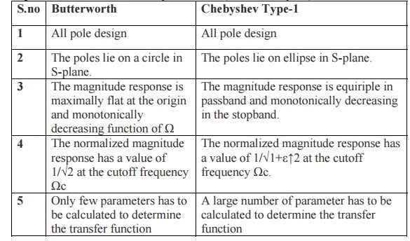
Butterworth
1. All pole design
2. The poles lie on a circle in S-plane.
3. The magnitude response is maximally flat at
the origin and monotonically decreasing function of Ω
4. The normalized magnitude response has a
value of 1/√2 at the cutoff frequency Ωc
5. Only few parameters has to be calculated to
determine the transfer function
Chebyshev
Type-1
1. All pole design
2. The poles lie on ellipse in S-plane.
3. The magnitude response is equiriple in
passband and monotonically decreasing in the stopband.
4. The normalized magnitude response has a
value of 1/√1+ε↑2 at the cutoff frequency Ωc.
5. A large number of parameter has to be
calculated to determine the transfer function
If H(s)=
Σ Ck / S-Pk then H(z) = Σ Ck / 1-ePkTZ-1
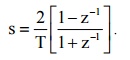
7. What is bilinear transformation?
The
bilinear transformation is a mapping that transforms the left half of s plane
into the unit circle in the z-plane only once, thus avoiding aliasing of
frequency components. The mapping from the s- plane to the z-plane in bilinear
transformation is s =
8.What is the main disadvantage of direct form-I
realization?
The
direct form realization is extremely sensitive to parameter quantization. When
the order of the system N is large, a small change in a filter coefficient due
to parameter quantization, results in a large change in the location of the
pole and zeros of the system.
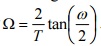
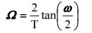
9.What is Prewarping?
The effect of the non-linear compression at high frequencies can
be compensated. When the desired magnitude response is piece-wise constant over
frequency, this compression can be compensated by introducing a suitable
prescaling, or prewarping the critical frequencies by using the formula, Ω=2/T tan ω/2.
10.List the features that make an analog to digital
mapping for IIR filter design coefficient.
The
bilinear transformation provides one-to-one mapping.
Stable
continuous systems can be mapped into realizable, stable digital systems.
There is
no aliasing.
In impulse invariant method, the mapping from s-plane to z-plane
is many to one i.e., all the poles in the s-plane between the intervals [(2k-1)π]/T to [(2k+1)π]/T ( for k=0,1,2……)
map into the entire z-plane. Thus, there are an infinite number of poles that
map to the same location in the z-plane, producing aliasing effect. Due to
spectrum aliasing the impulse invariance method is inappropriate for designing
high pass filters. That is why the impulse invariance method is not preferred
in the design of IIR filter other than low pass filters.
12.Find digital transfer function using approximate
derivative technique for the analog transfer function H(s)=1/s+3.Assume
T=0.1sec
H(z) = 1/
Z+e-0.3
13.Give the square magnitude function of
Butterworth filter.
The
magnitude function of the butter worth filter is given by
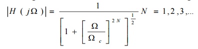
Where N
is the order of the filter and Ωc is the
cutoff
frequency.
The magnitude response of the butter worth filter closely approximates the
ideal response as the order N increases. The phase response becomes more
non-linear as N increases.
14. Find the digital transfer function H(z) by
using impulse invariant method for the analog transfer function
H(s)=1/s+1.Assume T=1sec.
H(z)= 1/
1-e-1z-1
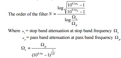
15.Give the equation for the order of N and cut-off
frequency Ωc of butter worth filter.
16.What are the properties of the bilinear
transformation?
The
mapping for the bilinear transformation is a one-to-one mapping; that is for
every point z, there is exactly one corresponding point s, and vice versa.
The
jΩ-axis maps on to the unit circle |z|=1, the left half of the s-plane maps to
the interior of the unit circle |z|=1 and the right half of the s-plane maps on
to the exterior of the unit circle |z|=1.
17.Write a short note on pre-warping.
The
effect of the non-linear compression at high frequencies can be compensated.
When the desired magnitude response is piece-wise constant over frequency, this
compression can be compensated by introducing a suitable pre-scaling, or
pre-warping the critical frequencies by using the formula. Ω =
18.What are the different types of structure for
realization of IIR systems?
The
different types of structures for realization of IIR system are
Direct-form-I
structure
Direct-form-II
structure
Transposed
direct-form II structure
Cascade
form structure
Parallel
form structure
Lattice-Ladder
structure
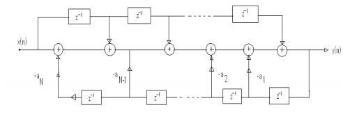
19.Draw the general realization structure in
direct-form I of IIR system.
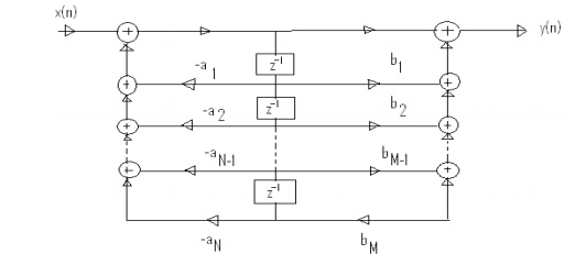
20.Give direct form II structure.
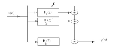
21.Draw the parallel form structure of IIR filter.
22.Mention any two techniques for
digitizing the transfer function of an analog filter.
The two techniques available for digitizing the analog filter transfer
function are Impulse invariant
transformation and Bilinear
transformation.
23.Write a brief notes on the design
of IIR filter. (Or how a digital IIR filter is designed?)
For designing a digital IIR filter, first an equivalent analog
filter is designed using any one of the approximation technique for the given
specifications. The result of the analog filter design will be an analog filter
transfer function Ha(s). The analog filter transfer function is transformed to
digital filter transfer function H(z) using either Bilinear or Impulse
invariant transformation.
24.Define an IIR filter
The filters designed by considering all the infinite samples of
impulse response are called IIR filers. The impulse response is obtained by
taking inverse Fourier transform of ideal frequency response.
25. Compare IIR and FIR filters.
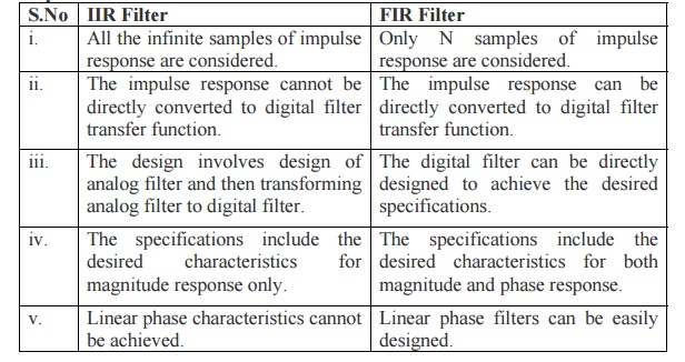
IIR Filter
i. All the infinite samples of impulse response are considered.
ii. The impulse response cannot be directly converted to digital
filter transfer function.
iii. The design involves design of analog filter and then
transforming analog filter to digital filter.
iv. The specifications include the desired characteristics for
magnitude response only.
v. Linear phase characteristics cannot be achieved.
FIR Filter
i. Only N samples of impulse response are considered.
ii. The impulse response can be directly converted to digital
filter transfer function.
iii. The digital filter can be directly designed to achieve the
desired specifications.
iv. The specifications include the desired characteristics for
both magnitude and phase response.
v. Linear phase filters can be easily designed.
GLOSSARY:
System Design:
Usually,
in the IIR Filter design, Analog filter is designed, then it is transformed to
a digital filter the conversion of Analog to Digital filter involves mapping of
desired digital filter specifications into equivalent analog filter.
Warping Effect:
The
analog Frequency is same as the digital frequency response. At high frequencies,
the relation between ω and Ω becomes Non-Linear. The Noise is introduced in the
Digital Filter as in the Analog Filter. Amplitude and Phase responses are
affected by this warping effect.
Prewarping:
The
Warping Effect is eliminated by prewarping of the analog filter. The analog
frequencies are prewarped and then applied to the transformation.
Infinite Impulse Response:
Infinite
Impulse Response filters are a Type of Digital Filters which has infinite
impulse response. This type of Filters are designed from analog filters. The
Analog filters are then transformed to Digital Domain.
Bilinear Transformation Method:
In
Bilinear transformation method the transform of filters from Analog to Digital
is carried out in a way such that the Frequency transformation produces a
Linear relationship between Analog and Digital Filters.
Filter:
A filter
is one which passes the required band of signals and stops the other unwanted
band of frequencies.
Pass band:
The Band
of frequencies which is passed through the filter is termed as passband.
Stopband:
The band
of frequencies which are stopped are termed as stop band.
Related Topics