Chapter: Graphics and Multimedia : Multimedia File Handling
Storage and Retrival Technology
STORAGE AND RETRIVAL TECHNOLOGY
Multimedia systems require
storage for large capacity objects such as video, audio and images.
Another requirement is
delivery of audio and video objects. Storage technologies include battery
powered RAM, Nonvolatile flash, rotating magnetic disk drives, and rotating
optical disk drives: Let us discuss these technologies in detail.
MAGNETIC MEDIA TECHNOLOGY
Magnetic hard disk drive
storage is a mass storage medium.
It has advantages of it
continual reduction in the price per mega byte of high-capacity storage. It has
high capacity and available in low cost.
In this section let us
concentrate on magnetic disk I/O subsystems most applicable to multimedia uses.
HARD DISK TECHNOLOGY
Magnetic hard disk storage
remains a much faster mass storage to play an important rol~ in multimedia
systems.
It remains a much faster mass
storage medium than any other mass storage medium.
ST506 and MFM Hard drives: ST506 is an interface that defines the
signals and the operation of signals between a hard disk controller and the
hard disk. It is developed by seagate. It is used to control platter speed and
the movement of heads for a drive. Parallel data is converted to a series of
encoded pulses by using a scheme called MFM (modified frequency modulation).
The MFM encoding scheme offers greater packing of bits and accuracy than the FM
encoding scheme. Other encoding scheme is Run-Length-Limited. Its drive
capacity varies from 20 M Bytes to 200 M Bytes.
ESDI Hard Drive: ESDI (Enhanced Small Device Interface) was developed by a
consortium of several manufacturers.
It converts the data into serial bit streams.
It uses the
Run-Length-Limited Scheme for encoding. The drive has data separator circuitry
Drive capacity varies from 80 M Bytes to 2 GB. ESDI interface has two ribbon
cables: (i) 36 pin cable for control signals. (ii) 20 pin cable for data
signals.
IDE: Integrated Device Electronics (IDE) contains a,n integrated
controller with drive.
The interface is 16 bit
parallel data interface. The IDE interface supports two IDE drives. One is
master drive and other is slave drive. Here, Jumper setting is required. The
transfer rate is 8 MHz at bus speed.
New Enhanced IDE Interface
This new interface has a
transfer rate of 9-13 M Bytes/See with maximum capacity around 8 GB. It
supports upto four drives CD ROM and tape drives.
SCSI (Small Computer System Interface)
It is an ANSI X3T9.2 standard
which supports SCSI and SCSI2 Standards. The Standard defines both software and
hardware.
SCSI-I:It defines an 8-bit parallel data path between host adapter and
device.
Here, host adapter is known
as initiator and the device is known as target. There are one initiator and
seven targets.
Nine control signals define
the activity phases of the SCSI bus during a transaction between an initiator
and a target. The phases are:
(i) arbitration phase (ii)
selection phase (iii) command phase (iv) data phase (v) status phase (vi)
message phase (vii) bus free phase.
Arbitrary Phase: In this phase an initiator starts arbitration and tries to
acquire the bus.
Selection Phase: In this phase, an initiator has acquired the bus and selects the
target to which it needs to
communicate.
Command Phase: The target now enters into this phase. It requests a command from
the initiator. Initiator places a
command on the bus. It is accepted by the target.
Data Phase: The target now enters in this phase. It requests data transfer
with the initiator. The data is placed
on the bus by the target and is then accepted by the initiator.
Status Phase: Now, the target enters in status phase. It indicates the end of
data transfer to the initiator. Message
Phase: This is the last phase. It is to interrupt the initiator signaling
completion of the read message. The
bus free phase is a phase without any activity on the bus so that the bus can
settle down before the next transaction. SCSI-l transfers data in 8-bit
parallel form, and the transfer rate vades rom I M Bytes/See to 5 M Bytes/Sec.
SCSI-I'drive capacity varies from 20 M bytes to 2 GB. SCSI-1 has over 64
commands specified to carry out transactions.
Commands include read, write,
seek, enquiry, copy, verify, copy and verify, compare and so on.
SCSI-2
It has the same aspects of
SCSI -1, But with faster data transfer . rates, and wider data width.
It includes few more new
commands, and vender-unique command sets for optical drives, tape drives,
scanners and so on. To make the bus wider, a system designer uses a second
68-pin connector in addition to the standard 50 pin connector.
Magnetic Storage Densities and Latencies
The Latency is divided into
two categories: seek latency and rotational latency. Data management provides
the command queuing mechanism to minimize latencies and also set-up the
scatter-gather process to gather scattered data in CPU main memory.
Seek Latencies: There are three seek latencies available. They are· overlapped
seek latency, Mid-transfer seek and Elevator seek.
Rotational Latencies: To reduce latency, we use two methods. They
are:
(i) Zero latency read/write:
Zero latency reads allow transferring data immediately after the head settles.
It does not wait for disk revolution to sector property.
(ii) Interleaving factor: It
keeps up with the data stream without skipping seccors. It determines the
organization of sectors.
Transfer Rate and I/O per Second: I/O transfer nite varies from 1.2 M
bytes/Sec. to 40 M bytes/Sec. Transfer
rate is defined as the rate at which data is transferred from the drive buffer
to the host adapter memory.
Data Management: It includes Command queueing and Scattergather. Command queueing
allows execution of multiple
sequential commands with system CPU intervention.Scatter is a process of
setting the data for best fit in available block of memory or disk. Gather is a
process which reassembles data into contiguous blocks on memory or disk ..
Figure below shows the
relationship between seek latency, Rotational latency and Data transfer
It is a method of attaching
multiple drives to a single host adapter. The data is written to the first drive
first, then after filling it, the controller, allow the data to write in second
drive, and so on. Meantime Between Failure (MTBF) = MTBF of single/drivel Total
no. of dr
RAID (Redundant Array of Inexpensive Disks)
It is an alternative to mass
storage for multimedia systems that combines throughput speed and reliability
improvements.
RAID is an array of multiple
disks. In RAID the data is spread across the drives. It achieves fault
tolerance, large storage capacity and performance improvement.
If we use RAID as our hot
backups, it will be economy. A number of RAID schemes havebeen developed:
1.Hot backup of
disk systems
2.Large volume
storage at lowercost
3.Higher
performance at lower cost
4.Ease of data
recovery
5.High MTBF.
There are six levels of RAID
available.
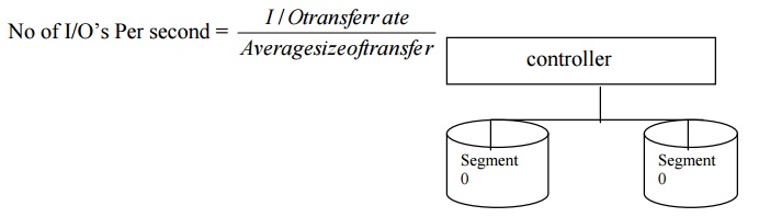
(i) RAID Level 0 Disk Striping
It spreads data across
drives. Data is striped to spread segments of data across multiple drives. Data
striping provides high transfer rate. Mainly, it is used for database
applications.
RAID level 0 provides
performance improvement. It is achieved by overlapping disk reads and writes.
Overlapping here means, while segment I is being written to drive 1, segment 2
writes can be initiated for drive 2.
RAID Level 1 Disk Mirroring
The Disk mirroring causes two
copies of every file to be written on two separate drives. (Data redundancy is
achieved).
These drives are connected to
a single disk controller. It is useful in mainframe and networking systems.
Apart from that, if one drive fails, the other drive which has its copy can be
used.
Performance: Writing is slow.
Reading can be speeded up by
overlapping seeks.
Read transfer rate and number
ofI/O per second is better than a single drive. I/O transfer rate (Bandwidth) =
No. of drives x drive I/O transfer rate
Disk controller arrangement
for RAID Level1
RAID Level 2, - Bit
interleaving of Data: It contains arrays of multiple drives connected-to a disk
array controller.
Data (written one bit at a
time) is bit interleaved across multiple drives. Multiple check disks are used
to detect and correct errors.
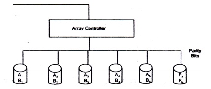
Host adapter organization of bit interleaving for RAID
level2
It provides the ability to
handle very large files, and a high level of integrity and reliability. It is
good for multimedia system. RAID Level 2 utilizes a hamming error correcting
code to correct single-bit errors and doublebit errors.
Drawbacks:
(i) It requires multiple
drives for error correction (ii) It is an expensive approach to data
redundancy. (iii) It is slow.
Uses: It is used in
multimedia system. Because we can store bulk of video and audio data.
RAID Level-3 Parallel Disk Array: RAID 3 subsystem contains an
array of multiple data drives and one
parity drive, connected to a disk array controller.
The difference between RAID 2
and RAID 3 is that RAID 3 employs only parity checking instead of the full
hamming code error detection and correction. It has the advantages of high
transfer rate, cost effective than RAID 2, and data integrity.
RAID Level-4 Sector Interleaving: Sector interleaving means writing successive
sectors of data on different drives.
As in RAID 3, RAID 4 employs
multiple data drives and typically a single dedicated parity drive. Unlike RAID
3, where bits of data are Written to successive disk drives, an Ri\ID 4, the
first sector of a block of data is written to the first drive, the second
sector of data is written to the secohd drive, and so on. The data is
interleaved at the data level.
RAID Leve1-4 offers cost-effective improvement in performance with data.
RAID Level-5 Block Interleaving: In RAID LevelS, as in all the other RAID
systems, multiple drives are
connected to a disk array controller.
The disk array controller
contains multiple SCSI channels.
A RAID 5 system can be designed
with a single SCSI host adapter with multiple drives connected to the single
SCSI channel.
Unlike RAID Level-4, where
the data is sector-interleaved, in RAID Level-5 the data is block-interleaved.
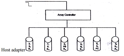
RAID LEVEL 5 DISK ARRAYS
Optical Media
CD ROM, WORM (Write once,
Read many) and rewritable optical systems are optical drives. ·CD-ROMs have
become the primary media of choice for music due to the quality of ,sound.
WORMs and erasable opticel drives both use lasers to pack
information densely on a
removable disk.
Optical Media can be classified by technology as follows:
·
CD-ROM - Compact Disc Read Only Memory
·
WORM - Write Once Read Many
·
Rewritable - Erasable
·
Multifunction - WORM and Erasable.
CD-ROM
Physical Construction of CD ROMs:
It consists of a
polycarbonate disk. It has 15 mm spindle hole in the center. The polycarbonate
substrate contains lands and pits.
The space between two
adjacent pits is called a land. Pits, represent binary zero, and the transition
from land to pits and from pits to land is represented by binary one.
The polycarbonate substrate
is covered by reflective aluminium or aluminium alloy or gold to increase the
reflectivity of the recorded surface. The reflective surface is protected by a
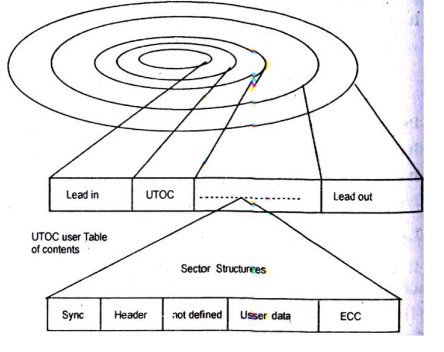
coat oflacquer to prevent oxidation. A CD-ROM consists of a single track which
starts at the center from inside and spirals outwards. The data is encoded on
this track in the form of lands and pits. A single track is divided into equal
length sectors and blocks.
CD-ROM Physical Layers
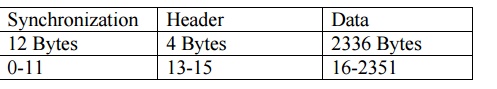
Each sector or block consists
of2352 bytes, also called a frame. For Audio CD, the data is indexed on
addressed by hours, rninutes, seconds and frames. There are 75 frames in a
second.
Magnetic Disk Organization: Magnetic disks are organized by CYlinder,
track and sector. Magnetic hard
disks contain concentric circular tracks. They are divided into sector.
Component of rewritable phase
change cd-rom
Organization of magnetic media
CD-ROM Standards : A number
of recording standards have emerged for CD-ROMs. They are:
CD-DA (DD-Digital Audio) Red Book: CD-ROM is developed by
philips and sony to store audio information.
CD-DA is the basic medium for the music industry.
The standard specifies
multiple tracks, with one song per track. One track contains one frame worth of
data: 2352 bytes. There are 75 frames in a second. Bandwidth = 176 KB/s.
CD-ROM Mode 1 Yellow Book: The Mode 1 Yellow Book Stnadard was developed
for error correction. The Yellow
Book Standard dedicates 288 bytes for error detection codes (EDCs) and error correction
codes (ECCs).
CD-ROM Mode 2 Yellow Book
The Mode 2 Yellow Book
standard was developed for compressed audio and video applications where, due
to lossy compression, data integrity is not quite as important. This standard
maintains the frame stmcture but it does not contain the ECC/EDC bytes. Removing the ECC/EDC
bytes allows a frame to contain an additional 288 bytes of data, resulting in
an increase of 14% more data. The frame stmcture is shown in the Table below:
CD-ROMXA
XA
stands for Extended Architecture. The standard was created for extending the
present CD-ROM format.
CD-ROM
XA contains multiple tracks. Each track's content is desclibed by mo~e. CD-ROM
XA also allows interleaving audio and video objects with data for synchroni~ed
playback. It does not support video compression. It supports audio compression.
It uses Adaptive differential pulse Code Modulation algorithms.
CD-MO Orange Book Part 1
This standard
defines an optional pre-mastered area conforming to the Red, Yellow or Green
book standards for read-only, and a recordable area. It utilizes a read/write
head similar to that found in magnetooptical drives. We can combine the
pre-master multimedia objects as the base and develop their own versions.
CD-R Orange Book Part 2
This
standard allows writing data once to a writeable disk. Here, the CD contains a
polycarbonate substrate with pits and lands.
The
polycarbonate layer is covered with an organic dye recording layer.
As in
CD-ROM construction, the track starts from the center and spirals outwards.
CD-R uses a high powered laser beam. The laser beam alters the state of the
organic dye such that when the data is read, the altered state of dye disperses
light instead of reflecting it. The reflected beam is measured for reading the
state of each bit on the disk.
Mini-Disk
Mini-Disk
for Data is known as MD-Data. It was developed by Sony Corporation. It is the
data version of the new rewritable storage format. It can be used in three
formats to support all users.
A
premastered optical disk.
A
recordable magneto-optical disk. A hybrid of mastered and recorded.
Its size
is 2.5 inch. It provides large capacity. It is low cost. It is used in multimedia
applications.
WORM Optical Drives
It
records data using a high power laser to create a permanent burnt-in record of
data. The laser beam makes permanent impressions on the surface of the disk.
It
creates pits. Information is written once. It cannot be written over and cannot
be erased. i.e., Here data cannot be edited.
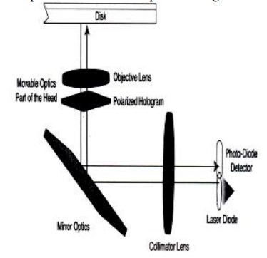
Recording of information: During recording, the input
Signal is fed to a laser diode. The laser beam from the laser diode is modulated by the inpUt signal. It switches
the laser beam on and off. if the beam is on, it strikes the three recording
layers.
The beam
is absorbed by the bismuth-tellurium layer. Heat is generated within the layer.
This heat diffuses the atoms in the three recording layers. It forms
four-element alloy layer. Now, the layer becomes recorded layers.
Reading Information from disk:
During disk read, a weaker,
laser beam is focused on to the disk. It is reflectted back. The beam splitter
mirror and lens arrangement sends the reflected beam to the photo detector. The
photo sensor detects the beam and converts it into an electrical signal.
WORM DRIVE Applications
On-line
catalogs Large-volume distribution Transaction logging Multimedia archival.
Rewritable Optical Disk Technologies
This technology allows
erasing old data and rewriting new data over old data. There are two types of
rewritable technology: (i) Magneto-optical ii)Phase change.
Magneto-Optical Technology
It uses a combination of
magnetic and laser technology to achieve read/write capability. The disk
recording layer uses a weak magnetic field to record data under high
temperature. High temperature is achieved by laser beam.
When the beam is on, it heats
the spot on the magneto optical disk to its curie temperature. The rise in temperature
makes the spot extra sensitive to the magnetic field of bias field.
Magneto-optical drives
require two passes to write data; in the first pass, the magneto optical head
goes through an erase cycle, and in the second pass, it writes the data.
During the erase cycle, the
laser beam is turned on and the bias field is modulated to change the polarity
of spots to be erased. During the write cycle, the bias field is turned on and
the laser beam is modulated to change the polarity of some spots to 1 according
to the bit value.
Phase change Rewritable optical Disk
In phase change technology
the recording layer changes the physical characteristics from crystalline to
amorphous and back under the influence of heat from a laser beam.
To read the data, a low power
laser beam is transmitted to the disk. The reflected beam is different for a
crystalline state than for an amorphous state. The difference in reflectivity
determines the polarity of the spot.
Benefits: it requires only one pass to write.
Dye Polymer Rewritable Disk
There is no need of magnetic
technology here.
This technology consists of
giant molecules formed from smaller molecules of the same kind with
light-sensitive dye. This technology is also used in WORM drives.
Related Topics