Chapter: Graphics and Multimedia : Multimedia File Handling
Compression and Decompression
COMPRESSION AND DECOMPRESSION
Compression is the way of making files to take up less space. In multimedia systems, in order to manage large multimedia data objects efficiently, these data objects need to be compressed to reduce the file size for storage of these objects.
Compression tries to eliminate redundancies in the pattern of data.
For example, if a black pixel is followed by 20 white pixels, there is no need to store all 20 white pixels. A coding mechanism can be used so that only the count of the white pixels is stored. Once such redundancies are removed, the data object requires less time for transmission over a network. This in turn significantly reduces storage and transmission costs.
TYPES OF COMPRESSION
Compression and decompression techniques are utilized for a number of applications, such as facsimile system, printer systems, document storage and retrieval systems, video teleconferencing systems, and electronic multimedia messaging systems. An important standardization of compression algorithm was achieved by the CCITT when it specified Group 2 compression for facsimile system. .
When information is compressed, the redundancies are removed.
Sometimes removing redundancies is not sufficient to reduce the size of the data object to manageable levels. In such cases, some real information is also removed. The primary criterion is that removal of the real information should not perceptly affect the quality of the result. In the case of video, compression causes some information to be lost; some information at a delete level is considered not essential for a reasonable reproduction of the scene. This type of compression is called lossy compression. Audio compression, on the other hand, is not lossy. It is called lossless compression.
Lossless Compression.
In lossless compression, data is not altered or lost in the process of compression or decompression. Decompression generates an exact replica ofthe original object. Text compression is a good example of lossless compression. The repetitive nature of text, sound and graphic images allows replacement of repeated strings of characters or bits by codes. Lossless compression techniques are good for text data and for repetitive data in images all like binary images and gray-scale images.
Some of the commonly accepted lossless standards are given below:
v Packpits encoding (Run-length encoding)
v CCITT Group 3 I D
v CCITT Group 3 2D
v CCITT Group 4
v Lempe l-Ziv and Welch algorithm LZW.
Lossy compression is that some loss would occur while compressing information objects.
Lossy compression is used for compressing audio, gray-scale or color images, and video objects in which absolute data accuracy is not necessary.
The idea behind the lossy compression is that, the human eye fills in the missing information in the case of video.
But, an important consideration is how much information can be lost so that the result should not affect. For example, in a grayscale image, if several bits are missing, the information is still perceived in an acceptable manner as the eye fills in the gaps in the shading gradient.
Lossy compression is applicable in medical screening systems, video tele-conferencing, and multimedia electronic messaging systems.
Lossy compressions techniques can be used alone o~' in combination with other compression methods in a multimedia object consisting of audio, color images, and video as well as other specialized data types.
The following lists some of the lossy compression mechanisms:
ü Joint Photographic Experts Group (JPEG)
ü Moving Picture Experts Group (MPEG)
ü Intel DVI
ü CCITT H.261 (P * 24) Video Coding Algorithm
ü Fractals.
Compression schemes are
Binary Image compression schemes
Binary Image Compression Scheme is a scheme by which a binary image containing black and white pixel is generated when a document is scanned in a binary mode.
The schemes are used primarily for documents that do not contain any continuous-tone information or where the continuous-tone information can be captured in a black and white mode to serve the desired purpose.
The schemes are applicable in office/business documents, handwritten text, line graphics, engineering drawings, and so on. Let us view the scanning process.A scanner scans a document as sequential scan lines, starting from the top of the page.
A scan line is complete line of pixels, of height equal to one pixel, running across the page. It scans the first line of pixels (Scan Line), then scans second "line, and works its way up to the last scan line of the page. Each scan line is scanned from left to right of the page generating black and white pixels for that scan line.
This uncompressed image consists of a single bit per pixel containing black and white pixels. Binary 1 represents a black pixel, binary 0 a white pixel. Several schemes have been standardized and used to achieve various levels of compressions. Let us review the more commonly used schemes.
1 .Packpits Encoding( Run-Length Encoding)
It is a scheme in which a consecutive repeated string of characters is replaced by two bytes. It is the simple, earliest of the data compression scheme developed. It need not to have a standard. It is used to compress black and white (binary) images. Among two bytes which are being replaced, the first byte contains a number representing the number of times the character is repeated, and the second byte contains the character itself.
In some cases, one byte is used to represent the pixel value, and the other seven bits to represents the run length.
2. CCITT Group 3 1-D Compression
This scheme is based on run-length encoding and assumes that a typical scanline has long runs of the same color.
This scheme was designed for black and white images only, not for gray scale or color images. The primary application of this scheme is in facsimile and early document imaging system.
Huffman Encoding
A modified version of run-length encoding is Huffman encoding.
It is used for many software based document imaging systems. It is used for encoding the pixel run length in CCITT Group 3 1-dGroup 4.
It is variable-length encoding. It generates the shortest code for frequently occurring run lengths and longer code for less frequently occurring run lengths.
Mathematical Algorithm for huffman encoding:
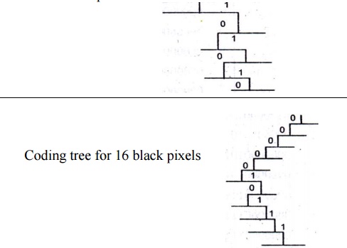
Huffman encoding scheme is based on a coding tree.
It is constructed based on the probability of occurrence of white pixels or black pixels in the run length or bit stream.
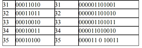
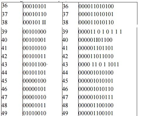
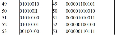
Table below shows the CCITT Group 3 tables showing codes or white run lengths and black run lengths.
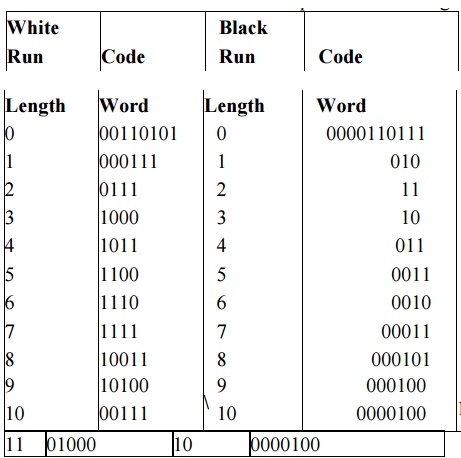
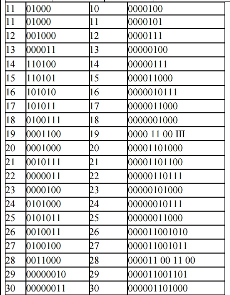
For example, from Table 2, the run-length code of 16 white pixels is 101010, and of 16 black pixels 0000010111. Statistically, the occurrence of 16 white pixels is more frequent than the occurrence of 16 black pixels. Hence, the code generated for 16 white pixels is much shorter. This allows for quicker decoding. For this example, the tree structure could be constructed.
The codes greater than a string of 1792 pixels are identical for black and white pixels. A new code indicates reversal of color, that is, the pixel Color code is relative to the color of the previous pixel sequence.
Table 3 shows the codes for pixel sequences larger than 1792 pixels.
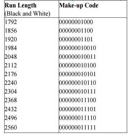
CCITT Group 3 compression utilizes Huffman coding to generate a set of make-up codes and a set of terminating codes for a given bit stream. Make-up codes are used to represent run length in multiples of 64 pixels. Terminating codes are used to represent run lengths of less than 64 pixels.
As shown in Table 2; run-length codes for black pixels are different from the run-length codes for white pixels. For example, the run-length code for 64 white pixels is 11011. The run length code for 64 black pixels is 0000001111. Consequently, the run length of 132 white pixels is encoded by the following two codes:
Makeup code for 128 white pixels - 10010 Terminating code for 4 white pixels - 1011
The compressed bit stream for 132 white pixels is 100101011, a total of nine bits. Therefore the compression ratio is 14, the ratio between the total number of bits (132) divided by the number of bits used to code them (9).
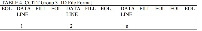
CCITT Group 3 uses a very simple data format. This consists of sequential blocks of data for each scanline, as shown in Table 4.
Coding tree for 16 white pixels
Note that the file is terminated by a number of EOLs (End of. Line) if there is no change in the line [rom the previous line (for example, white space).
TABLE 4: CCITT Group 3 1D File Format
Advantages of CCITT Group 3 ID
CCITT Group 3 compression has been used extensively due to the following two advantages: It is simple to implement in both hardware and software .
It is a worldwide standard for facsimile which is accepted for document imaging application. This allows document imaging applications to incorporate fax documents easily.
CCITT group 3 compressions utilizes Huffman coding to generate a set of make-up codes and a set of terminating codes for a give bit stream.
CCITT Group 3 uses a very simply data format. This consists of sequential blocks of data for each scanline.
CCITT Group 3 2D Compression
It is also known as modified run length encoding. It is used for software based imaging system and facsimile.
It is easier to decompress in software than CCITT Group 4. The CCITT Group 3 2D scheme uses a "k" factor where the
image is divided into several group of k lines. This scheme is based on the statistical nature of images; the image data across the adjacent scanline is redundant.
If black and white transition occurs on a given scanline, chances are the same transition will occur within + or - 3 pixels in the next scanline.
Necessity of k factor·
When CCITT Group 3 2D compression is used, the algorithm embeds Group 3 1 D coding between every k groups of Group 3 2D coding, allowing the Group 3 1 D coding to be the synchronizing line in the event of a transmission error.
Therefore when a transmission error occurs due to a bad communication link, the group 3 I D can be used to synchronize and correct the error.
Data formatting for CClIT Group 3 2D
The 2D scheme uses a combination of additional codes called vertical code, pass code, and horizontal code to encode every line in the group of k lines.
The steps for pseudocode to code the code line are:
(i) Parse the coding line and look for the change in the pixel value. (Change is found at al location).
(ii) Parse the reference line and look for the change in the pixel value. (Change is found at bl location).
(iii) . Find the difference in location between bland a 1: delta = b1- al
Advantage of CClIT Group 3 2D
The implementation of the k factor allows error-free
transmission . Compression ratio achieved is better than CClTT Group 3 1 D . It is accepted for document imaging applications.
![]() DisadvantageIt doesn’t provide dense compression
DisadvantageIt doesn’t provide dense compression
CCITT Group 4 2D compression
CClTT Group 4 compression is the two dimensional coding scheme without the k-factor.
In this method, the first reference line is an imaginary all-white line above the top of the image.The first group of pixels (scanline) is encoded utilizing the imaginary white line as the reference line.
The new coded line becomes the references line for the next scan line. The k-factor in this case is the entire page of line. In this method, there are no end-of-line (EOL) markers before the start of the compressed data
COLOR, GRAY SCALE AND STILL-VIDEO IMAGE COMPRESSION
Color:
Color is a part of life we take for granted. Color adds another dimension to objects. It helps in making things standout.
Color adds depth to images, enhance images, and helps set objects apart from -background.
Let us review the physics of color. Visible light is a form of electromagnetic radiation or radiant energy, as are radio frequencies or x-rays. The radiant energy spectrum contains audio frequencies, radio frequencies, infrared, visible light, ultraviolet rays, x-rays and gamma rays.
Radian energy is measured in terms of frequency or wavelength. The relationship between the two is
Color Characteristics
We typically define color by its brightness, the hue and depth of color.
Luminance or Brightness
This is the measure of the brightness of the light emitted or reflected by an object; it depends on the radiant, energy of the color band.
Hue This is the color sensation produced in an observer due to the presence of certain wavelengths of color. Each wavelength represents a different hue.
Saturation This is a measure of color intensity, for example, the difference between red and pink. Color Models Several calm' models have been developed to represent color mathematically. Chromacity Model It is a three-dimensional model with two dimensions, x and y, defining the color, and the third dimension defining the luminance. It is an additive model since x and yare added to generate different colors.
RGBModel RGB means Red Green Blue. This model implements additive theory in that different intensities of red, green and blue are added to generate various colors.
HSI Model The Hue Saturation and Intensity (HSI) model represents an artist's impression of tint, shade and tone. This model has proved suitable for image processing for filtering and smoothing images. CMYK Model The Cyan, Magenta, Yellow and Black color model is used in desktop publishing printing devices. It is a color-subtractive model and is best used in color printing devices only.
YUV Representation The NTSC developed the YUV three-dimensional color model. y -Luminance Component
UV -Chrominance Components.
Luminance component contains the black and white or grayscale information. The chrominance component contains color information where U is red minus cyan and V is megenta minus green.
YUV Model for JPEG
The JPEG compression scheme uses several stages.
The first stage converts the signal from the spatial RGB domain to the YUV frequency domain by performing discrete cosine transform. This process allows separating luminance or gray-scale components from the chrominance components of the image.
JOINT PHOTOGRAPHIC EXPERTS GROUP COMPRES5ION (JPEG)
ISO and CCITT working committee joint together and formed Joint Photographic Experts Group. It is focused exclusively on still image compression.
Another joint committee, known as the Motion Picture Experts Group (MPEG), is concerned with full motion video standards.
JPEG is a compression standard for still color images and grayscale images, otherwise known as continuous tone images.
JPEG has been released as an ISO standard in two parts
Part I specifies the modes of operation, the interchange formats, and the encoder/decoder specifies for these modes along with substantial implementation guide lines.
Part 2 describes compliance tests which determine whether the implementation of an encoder or decoder conforms to the standard specification of part I to ensure interoperability of systems compliant with JPEG standards
Requirements addressed by JPEG
The design should address image quality.
The compression standard should be applicable to practically any kind of continuous-tone digital source image .
It should be scalable from completefy lossless to lossy ranges to adapt it. It should provide sequential encoding .
It should provide for progressive encoding .
It should also provide for hierarchical encoding .
The compression standard should provide the option of lossless encoding so that images can be guaranteed to provide full detail at the selected resolution when decompressed.
Definitions in the JPEG Standard
The JPEG Standards have three levels of definition as follows:
* Base line system
* Extended system
* Special lossless function.
The base line system must reasonably decompress color images, maintain a high compression ratio, and handle from 4 bits/pixel to 16 bits/pixel.
The extended system covers the various encoding aspects such as variable-length encoding, progressive encoding, and the hierarchical mode of encoding.
The special lossless function is also known as predictive lossless coding. It ensures that at the resolution at which the image is no loss of any detail that was there in the original source image.
Overview of JPEG Components JPEG Standard components are:
(i) Baseline Sequential Codec
(ii) OCT Progressive Mode
(Hi) Predictive Lossless Encoding (iv) Hierarchical Mode.
These four components describe four four different levels of jPEG compression.
The baseline sequential code defines a rich compression scheme the other three modes describe enhancements to this baseline scheme for achieving different results.
Some of the terms used in JPEG methodologies are:
Discrete Cosine Transform (OCT)
OCT is closely related to Fourier transforms. Fourier transforms are used to represent a two dimensional sound signal.
DCT uses a similar concept to reduce the gray-scale level or color signal amplitudes to equations that require very few points to locate the amplitude in Y-axis X-axis is for locating frequency.
DCT Coefficients
The output amplitudes of the set of 64 orthogonal basis signals are called OCT Co-efficients. Quantization This is a process that attempts to determine what information can be safely discarded without a significant loss in visual fidelity. It uses OCT co-efficient and provides many-to-one mapping. The quantization process is fundamentally lossy due to its many-to-one mapping.
De Quantization This process is the reverse of quantization. Note that since quantization used a many-to-one mapping, the information lost in that mapping cannot be fully recovered
Entropy Encoder / Decoder Entropy is defined as a measure of randomness, disorder, or chaos, as well as a measure of a system's ability to undergo spontaneous change. The entropy encoder compresses quantized DCT co-efficients more compactly based on their spatial characteristics. The baseline sequential. codec uses Huffman coding. Arithmetic coding is another type of entropy encoding Huffman Coding Huffman coding requires that one or more sets of huff man code tables be specified by the application for encoding as well as decoding. The Huffman tables may be pre-defined and used within an application as defaults, or computed specifically for a given image.
Baseline Sequential codec
It consists of three steps: Formation of DCT co-efficients quantization, and entropy encoding. It is a rich compression scheme.
DCT Progressive Mode
The key steps of formation of DCT co-efficients and quantization are the same as for the baseline sequential codec. The key difference is that each image component is coded in multiple scans instead ofa single scan.
Predictive Lossless Encoding
It is to define a means of approaching lossless continuous-tone compression. A predictor combines sample areas and predicts neighboring areas on the basis of the sample areas. The predicted areas are checked against the fully loss less sample for each area.
The difference is encoded losslessly using huffman on arithmetic entropy encoding .
Hierarchical Mode
The hierarchical mode provides a means of carrying multiple resolutions. Each successive encoding of the image is reduced by a factor of two, in either the horizontal or vertical dimension.
JPEG Methodology
The JPEG compression scheme is lossy, and utilizes forward discrete cosine transform (or forward DCT mathematical function), a uniform quantizer, and entropy encoding. The DCT function removes data redundancy by transforming data from a spatial domain to a frequency domain; the quantizer quantizes DCT co-efficients with weighting functions to generate quantized DCT co-efficients optimized for the human eye; and the entropy encoder minimizes the entropy of quantized DCT co-efficients.
The JPEG method is a symmetric algorithm. Here, decompression is the exact reverse process of compression.
Figure below describes a typical DCT based encoder and decoder. Symmetric Operation of DCT based Codec
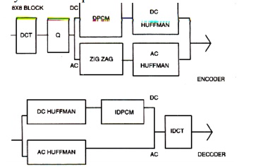
Figure below shows the components and sequence of quantization 5 * 8
Image blocks

Quantization
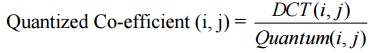
Quantization is a process of reducing the precision of an integer, thereby reducing the number of bits required to store the integer, thereby reducing the number of bits required to store the integer.
The baseline JPEG algorithm supports four color quantization tables and two huffman tables for both DC and AC DCT co-efficients. The quantized co-efficient is described by the following equation:
ZigZag Sequence
Run-length encoding generates a code to represent the C0unt of zero-value OCT co-efficients. This process of run-length encoding gives an excellent compression of the block consisting mostly of zero values.
Further empirical work proved that the length of zero values in a run can be increased to give a further increase in compression by reordering the runs. JPEG came up with ordering the quantized OCT co-efficients in a ZigZag sequence
Entropy Encoding
Entropy is a term used in thermodynamics for the study of heat and work. Entropy, as used in data compression, is the measure of the information content of a message in number of bits. It is represented as
Entropy in number of bits = log2 (probability of Object)
VIDEO IMAGE COMPRESSION
The development of digital video technology has made it possible to use digital video compression for a variety of telecommunications applications. Standardization of compression algorithms for video was first initiated by CCITT for teleconferencing and video telephony
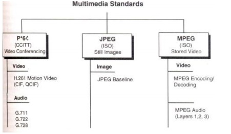
Multimedia standards for Video:
Requirements for full-motion Video Compression
Applications using MPEG standards can be symmetric or asymmetric. Symmetric applications are applications that require essentially equal use of compression and decompression. Asymmetric applications require frequent decompression.
Symmetric applications require on-line input devices such as video cameras, scanners and microphones for digitized sound. In addition to video and audio compression, this standards activity is concerned with a number of other Issues concerned with playback of video clips and sound clips. The MPEG standard has identified a number of such issues that have been addressed by the standards activity. Let us review these Issues.
Random Access
The expectations generated for multimedia systems are the ability to playa sound or video clip from any frame with that clip, irrespective of on what kind-of media the information is stored
VCR paradigm
The VCR paradigm consists of the control functions typically found on a VCR such as play, fast forward, rewind, search forward and rewind search.
Multiplexing Multiple Compressed Audio and Video Bit Streams
It is a special requirement retrieved from different storage centers on a network. It may be received from different storage centers on a network. It may have to be achieved in a smooth manner to avoid the appearance of a jumpy screen.
Editability
Playback Device Flexibility
CCITT H.261 Video Coding Algorithms (P x 64)
The linear quantizer uses a step algorithm that can be adjusted based on picture quality and coding efficiency. The H.261 is a standard that uses a hybrid of OCT and OPCM (differential pulse Code Modulation) schemes with motion estimation.
It also defines the data format. Each MB contains the OCT coefficients (TCOEFF) ofa block followed by an EOB (a fixed length end-of-block marker). Each MB consists of block data and an MB header. A GOB (Group of Blocks) consists of a GOB header. The picture layer consists of a picture header. The H.261 is designed for dynamic use and provides a fully contained organization and a high level of interactive control.
Moving Picture Experts Group Compression
The MPEG standards consist of a number of different standards.
The MPEG 2 suite of standards consist of standards for MPEG2 Video, MPEG - 2 Audio and MPEG - 2 systems. It is also defined at different levels, called profiles.
The main profile is designed to cover the largest number of applications. It supports digital video compression in the range of2 to 15 M bits/sec. It also provides a generic solution for television worldwide, including cable, direct broadcast satellite, fibre optic media, and optical storage media (including digital VCRs).
MPEG Coding Methodology
The above said requirements can be achieved only by incremental coding of successive frames. It is known as interframe coding. If we access information randomly by frame requires coding confined to a specific frame, then it is known as intraframe coding.
The MPEG standard addresses these two requirements by providing a balance between interframe coding and intraframe coding. The MPEG standard also provides for recursive and non-recursive temporal redundancy reduction.
The MPEG video compression standard provides two basic schemes: discrete-transform-based compression for the reduction of' spatial redundancy and block-based motion compensation for the reduction of temporal (motion) redundancy. During the initial stages of DCT compression, both the full motion MPEG and still image JPEG algorithms are essentially identical. First an image is converted to the YUVcolor space (a luminance/chrominance color space similar to that used for color television). The pixel data is then fed into a discrete cosine transform, which creates a scalar quantization (a two-dimensional array representing various frequency ranges represented in the image) of the pixel data.
Following quantization, a number of compression algorithms are applied, including run-length and Huffman encoding. For full motion video (MPEG I and 2), several more levels of block based motion-compensated techniques are applied to reduce temporal redundancy with both causal and noncausal coding to further reduce spatial redundancy.
The MPEG algorithm for spatial reduction is lossy and is defined as a hybrid which employs motion compensation, forward discrete cosine transform (DCF), a uniform quantizer, and Huffman coding. Block-based motion compensation is utilized for reducing temporal redundancy (i.e. to reduce the amount of data needed to represent each picture in a video sequence). Motion-compensated reduction is a key feature of MPEG.
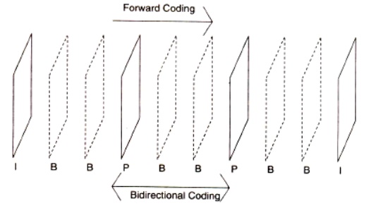
Moving Picture Types
Moving pictures consist of sequences of video pictures or t1'ame'S that are played back a fixed number of frames per second. To achieve the requirement of random access, a set of pictures can be defined to form a group of pictures (GOP) consisting of one or more of the following three types of pictures.
Intra pictures (1)
Undirectionally predicted pictures (U) Bidirectiomflly predicted pictures (B)
A Gap consists of consecutive pictures that begin with an intrapicture. The intrapicture is coded without any reference to any other picture in the group.
PrediGted pictures are coded with a reference to a past picture, either an intrapicture or a unidirectionally predicted picture. Bidirectionally predicted picture is never used as referencesMotion Compensation for Coding MPEG
Let us review the concept of Macroblocks and understand the role they play in compression
MACRO BLOCKS
For the video coding algorithm recommended by CCITT, CIF and QCIF are diviqed into a hierarchical block structure consisting of pictures, groups of blocks (GOBs), Macro Blocks(MBs), and blocks. Each picture frame is divided into 16 x 16 blocks. Each Macroblock is composed of four 8 x 8 (Y) luminance blocks and two 8 x 8 (Cb and Cn) chrominance blocks. This set of six blocks, called a macroblock; is the basic hierarchical component used for achieved a high level of compression.
Motion compensation
Motion compensation is the basis for most compression algorithms for visual telephony and full-motion video. Motion compensation assumes that the current picture is some translation of a previous picture. This creates the opportunity for using prediction and interpolation. Prediction requires only the current frame and the reference frame.
Based on motion vectors values generated, the prediction approach attempts to find the relative new position of the object and confirms it by comparing some block exhaustively. In the interpolation approach, the motion vectors are generated in relation to two reference frames, one from the past and the next predicted frame.
The best-matching blocks in both reference frames are searched, and the average is taken as the position of the block in the current frame. The motion vectors for the two reference, frames are averaged.
Picture Coding Method
In this coding method, motion compensation is applied bidirectionally. In MPEG terminology, the motion-compensated units are called macro blocks (MBs).
MBs are 16 x 16 blocks that contain a number of 8 x 8 luminance and chrominance blocks. Each 16 x 16 macro block can be of type intrapicture, forward-predicted, backward predicted, or average.
MPEG Encoder
Figure below shows the architecture of an MPEG encoder. It contains DCT quantizer, Huffman coder and Motion compensation. These represent the key modules in the encoder.
Architecture of MPEG Encoder:
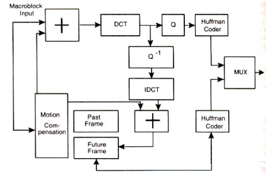
The Sequence of events for MPEG
First an image is converted to the YUV color space.
The pixel data is then fed into a DCT, which creates a scalar quantization of the pixel data.
Following quantization, a number of compression algorithms are applied, including run-length and Huffman encoding. For full-motion video, several more levels of motion compensation compression and coding are applied.
MPEG -2
It is defined to include current television broadcasting compression and decompression needs, and attempts to include hooks for HDTV broadcasting.
The MPEG-2 Standard Supports:
1.Video Coding: * MPEG-2 profiles and levels.
2.Audio Coding:*MPEG-l audio standard fro backward compatibility.
* Layer-2 audio definitions for MPEG-2 and stereo sound.
* Multichannel sound.
3. Multiplexing: MPEG-2 definitions
MPEG-2, "The Grand Alliance"
It consists of following companies AT&T, MIT, Philips, Sarnoff Labs, GI Thomson, and Zenith.
The MPEG-2committee and FCC formed this alliance. These companies together have defined the advanced digital television system that include the US and European HDTV systems. The outline of the advanced digital television system is as follows:
1.Format: 1080/2: 1160 or 720/1.1160
2.Video coding: MPEG-2 main profile and high level 3.Audio coding: Dolby AC3
4.Multiplexor: As defined in MPEG-2
Modulation: 8- VSB for terrestrial and 64-QAM for cable.
Vector Quantization
Vector quantization provides a multidimensional representation of information stored in look-up tables, vector quantization is an efficient pattern-matching algorithm in which an image is decomposed into two or more vectors, each representing particular features of the image that are matched to a code book of vectors.
These are coded to indicate the best fit.
In image compression, source samples such as pixels are blocked into vectors so that each vector describes a small segment or sub block of the original image.
The image is then encoded by quantizing each vector separately
Intel's Indeo Technology
It is developed by Intel Architecture Labs Indeo Video is a software technology that reduces the size of uncompressed digital video files from five to ten times.
Indeo technology uses multiple types of 'lossy' and 'lossless' compression techniques.
AUDIO COMPRESSION
Audio consists of analog signals of varying frequencies. The audio signals are converted to digital form and then processed, stored and transmitted. Schemes such as linear predictive coding and adaptive differential. pulse code modulation (ADPCM) are utilized for compression to achieve 40-80% compression.
FRACTAL COMPRESSION
A fractal is a multi-dimensional object with an irregular shape or body that has approximately the same shape or body irrespective of size. For example, if you consider 'stick' as your object, the fractal is defined, mathematically as
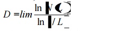
where L - approaches 0,
N(L) ~ number of stick L, and L is the length of the stick.
Related Topics