Chapter: Graphics and Multimedia : Multimedia File Handling
Digital Voice and Audio
DIGITAL VOICE AND AUDIO
Digital Audio
Sound is made up of
continuous analog sine waves that tend to repeat depending on the music or
voice. The analog waveforms are converted into digital fornlat by
analog-to-digital converter (ADC) using sampling process.
Sampling process
Sampling is a process where
the analog signal is sampled over time at regular intervals to obtain the
amplitude of the analog signal at the sampling time.
Sampling rate
The regular interval at which
the sampling occurs is called the sampling rate.
Digital Voice
Speech is analog in nature
and is cOl1veli to digital form by an analog-to-digital converter (ADC). An ADC
takes an input signal from a microphone and converts the amplitude of the
sampled analog signal to an 8, 16 or 32 bit digital value.
The four important factors
governing the
ADC process are sampling
rate resolution linearity and conversion speed.
Sampling Rate: The rate at which the ADC takes a sample of an analog signal. Resolution: The number of bits
utilized for conversion determines the resolution of ADC.
Linearity: Linearity implies that the sampling is linear at all frequencies
and that the amplitude tmly represents
the signal.
Conversion Speed: It is a speed of ADC to convert the analog
signal into Digital signals. It must be fast enough.
VOICE Recognition System
Voice Recognition Systems can
be classified into three types. 1.Isolated-word Speech Recognition.
2.Connected-word
Speech Recognition.
3.Continuous Speech
Recognition.
1. Isolated-word Speech
Recognition.
It provides recognition of a
single word at a time. The user must separate every word by a pause. The pause
marks the end of one word and the beginning of the next word.
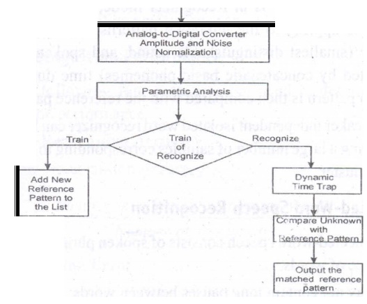
Stage 1: Normalization
The recognizer's first task
is to carry out amplitude and noise normalization to minimize the variation in
speech due to ambient noise, the speaker's voice, the speaker's distance from
and position relative to the microphone, and the speaker's breath noise.
Stage2: Parametric Analysis
It is a preprocessing stage
that extracts relevent time-varying sequences of speech parameters. This stage
serves two purposes: (i) It extracts time-varying speech parameters. (ii) It
reduces the amount of data of extracting the relevant speech parameters.
Training modeIn training mode of the recognizer, the new frames are added to the
reference list. Recognizer modeIf
the recognizer is in Recognizer mode, then dynamic time warping is applied to
the unknown patterns to average out
the phoneme (smallest distinguishable sound, and spoken words are constructed
by concatenatic basic phonemes) time duration. The unknown pattern is then
compared with the reference patterns.
A speaker independent
isolated word recognizer can be achieved by groupi.ng a large number of samples
corresponding to a word into a single cluster.
2Connected-Word Speech RecognitionConnected-word speech
consists of spoken phrase consisting of
a sequence of words. It may not contain long pauses between words.
The method using Word Spotting technique
It Recognizes words in a
connected-word phrase. In this technique, Recognition is carried out by
compensating for rate of speech variations by the process called dynamic time
warping (this process is used to expand or compress the time duration of the
word), and sliding the adjusted connected-word phrase representation in time
past a stored word template for a likely match.
Continuous Speech Recognition
This sytem can be divided
into three sections:
(i)
A section consisting of digitization, amplitude normalization, time
nonnalization and parametric representation.
(ii)
Second section consisting of segmentation and labeling of the
speech segment into a symbolic string based on a knowledgebased or rule-based
systems.
(iii)
The final section is to match speech segments to recognize word
sequences.
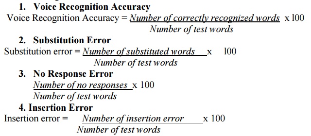
Voice Recognition performance
It is categorized into two
measures: Voice recognition performance and system performance. The following
four measures are used to determine voice recognition performance.
Voice Recognition Applications
Voice mail integration: The
voice-mail message can be integrated with e-mail messages to create an
integrated message.
DataBase Input and Query Applications
A number of applications are
developed around the voice recognition and voice synthesis function. The
following lists a few applications which use Voice recognition.
•
Application such as order entry and tracking
It is a server function; It
is centralized; Remote users can dial into the system to enter an order or to
track the order by making a Voice query.
•
Voice-activated rolodex or address book
When a user speaks the name
of the person, the rolodex application searches the name and address and
voice-synthesizes the name, address, telephone numbers and fax numbers of a
selected person. In medical emergency, ambulance technicians can dial in and
register patients by speaking into the hospital's centralized system.
Police can make a voice query
through central data base to take follow-up action ifhe catch any suspect.
Language-teaching systems are
an obvious use for this technology. The system can ask the student to spell or
speak a word. When the student speaks or spells the word, the systems performs
voice recognition and measures the student's ability to spell. Based on the
student's ability, the system can adjust the level of the course. This creates
a self-adjustable learning system to follow the individual's pace.
Foreign language learning is
another good application where"' an individual student can input words and
sentences in the system. The system can then correct for pronunciation or
grammar.
Musical Instrument Digital Interface (MIDI)
MIDI interface is developed
by Daver Smith of sequential circuits, inc in 1982. It is an universal
synthesizer interface
MIDI Specification 1.0
MIDI is a system
specification consisting of both hardware and software ~omponents which define
inter-coimectivity and a communication protocol for electronic sysnthesizers,
sequences, rythm machines, personal computers, and other electronic musical
instruments. The inter-connectivity defines the standard cabling scheme,
connector type and input/output circuitry which enable these different MIDI
instruments to be interconnected. The communication protocol defines standard
multibyte messages that allow controlling the instrument"s voice and
messages including to send response, to send status and to send exclusive.
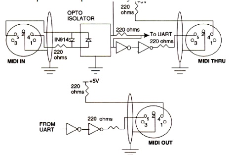
MIDI Hardware Specification
The MIDI. hardware
specification require five pin panel mount requires five pin panel mount
receptacle DIN connectors for MIDI IN, MIDI OUT and MIDI THRU signals. The MIDI
IN connector is for input signals The MIDI OUT is for output signals MIDI THRU
connector is for daisy-chaining multiple MIDI instruments.
MIDI Interconnections
The MIDI IN port of an
instrument receives MIDI ncssages to play the instrument's internal synthesizer.
The MIDI OUT port sends MIDI messages to play these messages to an external
synthesizer. The MIDI THRU port outputs MIDI messages received by the MIDI IN
port for daisy-chaining external synthesizers.
MIDI Input and output
circuitry:
Communication Protocol
The MIDI communication
protocol uses multibyte messages; There are two types of messages:
(i) Channel messages
(ii)
System messages.
The channel message have
three bytes. The first byte is called a status byte, and the other two bytes
are called data bytes.
The two types of channel messages: (i) Voice messages
(ii) Mode messages.
System messages: The three
types of system messages.
Common message: These
messages are common to the complete system. These messages provide for functions.
System real.time messages:
These messages are used for setting the system's real-time parameters. These
parameters include the timing clock, starting and stopping the sequencer,
resuming the sequencer from a stopped position and restarting the system.
System exclusive message:
These messages contain manufacturer specific data such as identification,
serial number, model number and other information.
SOUND BOARD ARCHITECTURE
A sound card consist of the following
components:
MIDI Input/Output Circuitry,
MIDI Synthesizer Chip, input mixture circuitry to mix CD audio input with LINE
IN input and microphone input, analog-to-digital converter with a pulse code
modulation circuit to convert analog signals to digital to create WAVfiles, a
decompression and compression chip to compress and decompress audio files, a
speech synthesizer to synthesize speech output, a speech recognition circuitry
to recognize speech input and output circuitry to output stereo audio OUT or
LINEOUT.
AUDIO MIXER
The audio mixer c:omponent of
the sound card typically has external inputs for stereo CD audio, stereo LINE
IN, and stereo microphone MICIN.
These are analog inputs, and
they go through analog-to-digitaf conversion in conjunction with PCM or ADPCM
to generate digitized samples.
SOUND BOARD ARCHITECTURE:
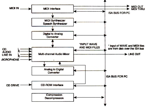
Analog-to-Digital Converters: The ADC gets its input from the audio mixer
and converts the amplitude of a
sampled analog signal to either an 8-bit or 16-bit digital value.
Digital-to-Analog Converter (DAC): A DAC converts digital input in the
'foml of W AVE files, MIDI output
and CD audio to analog output signals.
Sound Compression and
Decompression: Most sound boards include a codec for sound compression and
decompression.
ADPCM for windows provides
algorithms for sound compression.
CD-ROM Interface: The CD-ROM interface allows connecting u CD
ROM drive.to the sound board.
VIDEO IMAGES AND ANIMATION
VIDEO FRAME GRABBER ARCHITECTURE
A video frame grabber is used
to capture, manipulate and enhance video images.
A video frame grabber card
consists of video channel multiplexer, Video ADC, Input look-up table with
arithmetic logic unit, image frame buffer, compression-decompression circuitry,
output color look-up table, video DAC and synchronizing circuitry.
Video Channel Multiplexer:
A video channel multiplexer
has multiple inputs for different video inputs. The video channel multiplexer
allows the video channel to be selected under program control and switches to
the control circuitry appropriate for the selected channel in aTV with multi –
system inputs.
Analog to Digital Converter:
The ADC takes inputs from video multiplexer and converts the amplitude of a
sampled analog signal to either an 8-bit digital value for monochrome or a 24
bit digital value for colour.
Input lookup table: The input lookup table along with the
arithmetic logic unit (ALU) allows performing
image processing functions on a pixel basis and an image frame basis. The pixel
image-processing functions ate histogram stretching or histogram shrinking for
image brightness and contrast, and histogram sliding to brighten or darken the
image. The frame-basis image-processing functions perform logical and
arithmetic operations.
Image Frame Buffer Memory: The image frame buffer is organized as a l024
x 1024 x 24 storage buffer to store
image for image processing and display.
Video Compression-Decompression: The video compressiondecompression processor
is used to compress and decompress
still image data and video data.
Frame Buffer Output Lookup Table: The frame buffer data represents the pixel
data and is used to index into the output look uptable. The output lookup table
generates either an 8 bit pixel value for monochrome or a 24 bit pixel value
for color.
SVGA Interface: This is an optional interface for the frame
grabber. The frame grabber can be designed
to include an SVGA frame buffer with its own output lookup table and
digital-to-analog converter.
Analog Output Mixer: The output from the SVGA DAC and the output
from image frame buffer DAC is mixed
to generate overlay output signals. The primary components involved include the
display image frame buffer and the display SVGA buffer. The display SVGA frame
buffer is overlaid on the image frame buffer or live video, This allows SVGA to
display live video.
Video and Still Image Processing
Video image processing is
defined as the process of manipulating a bit map image so that the image can be
enhanced, restored, distorted, or analyzed.
Let us discuss about some of
the terms using in video and still image processing.
Pixel point to point processing: In pixel point-to-point processing, operations
are carried out on individual pixels
one at a time.
Histogram Sliding: It is used to change the overall visible effect
of brightening or darkening of the image.
Histogram sliding is implemented by modifying the input look-up table values
and using the input lookup table in conjunction with arithmetic logic unit.
Histogram Stretching and Shrinking: It is to increase or decrease
the contrast.
In histogram shrinking, the
brighter pixels are made less bright and the darker pixels are made less dark. Pixel Threshold: Setting pixel
threshold levels set a limit on the bright or dark areas of a picture. Pixel threshold setting is also achieved
through the input lookup table.
Inter- frame image processing
Inter- frame image processing
is the same as point-to-point image processing, except that the image processor
operates on two images at the same time. The equation of the image operations
is as follows: Pixel output (x, y) = (Image l(x, y)
Operator (Image 2(x, y)
Image Averaging: Image
averaging minimizes or cancels the effects of random noise.
Image Subtraction: Image
subtraction is used to determine the change from one frame to the next .for
image comparisons for key frame detection or motion detection.
Logical Image Operation: Logical image processing operations are useful
for comparing image frames and
masking a block in an image frame.
Spatial Filter Processing The rate of change of shades
of gray or colors is called spatial frequency. The process of generating images with either low-spatial
frequency-components or high frequency components is called spatial filter
processing.
Low Pass Filter: A low pass filter causes blurring of the image
and appears to cause a reduction in noise.
High Pass Filter: The high-pass filter causes edges to be
emphasized. The high-pass filter attenuates
low-spatial frequency components, thereby enhancing edges and sharpening
the image.
Laplacian Filter: This filter sharply attenuates
low-spatial-frequency components without affecting and high-spatial frequency components, thereby enhancing edges
sharply.
Frame Processing Frame processing operations are most commonly
for geometric operations, image transformation,
and image data compression and decompression Frame processing operations are
very compute intensive many multiply and add operations, similar to spatial
filter convolution operations.
Image scaling: Image scaling allows enlarging or shrinking the whole or part of an
image.
Image rotation: Image rotation allows the image to be rotated about a center
point. The operation can be used to
rotate the image orthogonally to reorient the image if it was scanned
incorrectly. The operation can also be used for animation. The rotation formula
is:
pixel output-(x, y) = pixel input (x, cos Q + y sin Q, - x sin Q + Y cos Q) where, Q is the
orientation angle
x, yare the spatial co-ordinates of the original pixel.
Image translation: Image translation allows the image to be moved
up and down or side to side. Again, this
function can be used for animation.
The translation formula is:
Pixel output (x, y) =Pixel Input (x + Tx, y + Ty) where
Tx and Ty are the horizontal
and vertical coordinates. x, yare the
spatial coordinates of the original pixel.
Image transformation: An image contains varying degrees of brightness
or colors defined by the spatial
frequency. The image can be transformed from spatial domain to the frequency
domain by using frequency transform.
Image Animation Techniques
Animation: Animation is an illusion of movement created by sequentially
playing still image frames at the
rate of 15-20 frames per second.
Toggling between image frames: We can create simple animation by changing
images at display time. The simplest
way is to toggle between two different images. This approach is good to
indicate a "Yes" or "No" type situation.
Rotating through several image frames: The animation contains
several frames displayed in a loop. Since
the animation consists of individual frames, the playback can be paused and
resumed at any time.
Related Topics