Chapter: Microprocessor and Microcontroller : Interfacing Microcontroller
Stepper Motor Interface
Stepper Motor Interface
The
complete board consists of transformer, control circuit, keypad and stepper
motor as shown in snap.
The
circuit has inbuilt 5 V power supply so when it is connected with transformer
it will give the supply to circuit and motor both. The 8 Key keypad is
connected with circuit through which user can give the command to control
stepper motor. The control circuit includes micro controller 89C51, indicating
LEDs, and current driver chip ULN2003A. One can program the controller to
control the operation of stepper motor. He can give different commands through
keypad like, run clockwise, run anticlockwise, increase/decrease RPM, increase/decrease
revolutions, stop motor, change the mode, etc. Unipolar stepper motor:-unipolar stepper motor has four coils. One
end of each coil is tied together and it gives common terminal which is always
connected with positive terminal of supply. The other ends of each coil are
given for interface. Specific color code may also be given. Like in my motor
orange is first coil (L1), brown is second (L2), yellow is third (L3), black is
fourth (L4) and red for common terminal.
By means
of controlling a stepper motor operation we can
1. Increase
or decrease the RPM (speed) of it
2. Increase
or decrease number of revolutions of it
3. Change
its direction means rotate it clockwise or anticlockwise
To vary the RPM of motor we have to vary the PRF
(Pulse Repetition Frequency). Number of applied pulses will vary number of
rotations and last to change direction we have to change pulse sequence.
So all
these three things just depends on applied pulses. Now there are three
different modes to rotate this motor
1. Single coil
excitation
2. Double
coil excitation
3. Half step
excitation
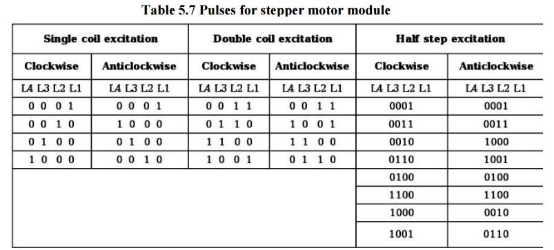
The table
given below will give you the complete idea that how to give pulses in each
mode
Table 5.7 Pulses for stepper motor module
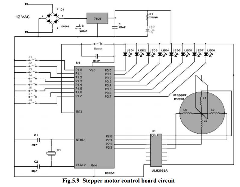
The
circuit consists of very few components. The major components are 7805, 89C51
and ULN2003A.
Connections:-
1. The
transformer terminals are given to bridge rectifier to generate rectified DC.
2. It is
filtered and given to regulator IC 7805 to generate 5 V pure DC. LED indicates
supply is ON.
3. All the
push button micro switches J1 to J8 are connected with port P1 as shown to form
serial keyboard.
4. 12 MHz
crystal is connected to oscillator terminals of 89C51 with two biasing
capacitors.
5. All the
LEDs are connected to port P0 as shown
6. Port P2
drives stepper motor through current driver chip ULN2003A.
7. The
common terminal of motor is connected to Vcc and rest all four terminals are
connected to port P2 pins in sequence through ULN chip.
Related Topics