Chapter: Microprocessor and Microcontroller : Interfacing Microcontroller
Programming 8051 Timers: Using Timers to Measure Time
Programming 8051 Timers: Using Timers to Measure
Time
One of
the primary uses of timers is to measure time.
When a
timer is in interval timer mode (as opposed to event counter mode) and
correctly configured, it will increment by 1 every machine cycle. A single
machine cycle consists of 12 crystal pulses. Thus a running timer will be
incremented:11,059,000 / 12 = 921,583 times per second.
Unlike
instructions which require 1 machine cycle, others 2, and others 4--the timers
are consistent: They will always be incremented once per machine cycle. Thus if
a timer has counted from 0 to 50,000 you may calculate:
50,000 /
921,583 = .0542.0542 seconds have passed. To execute an event once per second
you’d have to wait for the timer to count from 0 to 50,000 18.45times.
To
calculate how many times the timer will be incremented in .05 seconds, a simple
multiplication can be done: 0 .05 * 921,583 = 46,079.15.
This
tells us that it will take .05 seconds (1/20th of a second) to count from 0 to
46.0. To work with timers is to control the timers and initialize them.
The TMOD SFR
TMOD
(Timer Mode): The TMOD SFR is used to control the mode of operation of both
timers. Each bit of the SFR gives the microcontroller specific information
concerning how to run a timer. The high four bits (bits 4 through 7) relate to
Timer 1whereas the low four bits (bits 0 through 3) perform the exact same
functions, but for timer 0. The modes of operation are:
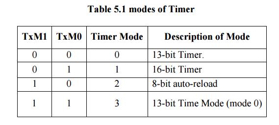
Timer
mode "0" is a 13-bit timer. When the timer is in 13-bit mode, TLx
will count from 0 to 31. When TLx is incremented from 31, it will
"reset" to 0 and increment THx. Thus, effectively, only 13 bits of
the two timer bytes are being used: bits 0-4 of TLx and bits 0-7 of THx. The
timer can only contain 8192 values. If you set a 13-bit timer to 0, it will overflow
back to zero 8192 machine cycles later.
16-bit Time Mode (mode 1)
Timer
mode "1" is a 16-bit timer. TLx is incremented from 0 to 255. When
TLx is incremented from 255, it resets to 0 and causes THx to be incremented by
1. Since this is a full 16-bit timer, the timer may contain up to 65536
distinct values. If you set a 16-bit timer to 0, it will overflow back to 0
after 65,536 machine cycles.
8-bit Time Mode (mode 2)
Timer
mode "2" is an 8-bit auto-reload mode.
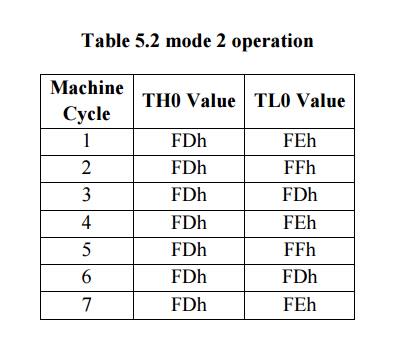
When a
timer is in mode 2, THx holds the "reload value" and TLx is the timer
itself. Thus, TLx starts counting up. When TLx reaches 255 and is subsequently
incremented, instead of resetting to 0 (as in the case of modes 0 and 1), it
will be reset to the value stored in THx. For example, if TH0 holds the value
FDh and TL0 holds the value FEh values of TH0 and TL0 for a few machine cycles:
The value
of TH0 never changed. When we use mode 2 you almost always set THx to a
known value and TLxis the SFR that is constantly
incremented. The benefit of auto-reload mode is the timer always have a value
from 200 to 255. If you use mode 0 or 1, you’d have
to check
in code to see if the timer had overflowed and, if so, reset the timer to 200.
This takes precious instructions of execution time to check the value and/or to
reload it. When
you use
mode 2 the microcontroller takes care of this. Auto-reload mode is very
commonly used for establishing a baud rate in Serial Communications.
Split Timer Mode (mode 3)
Timer
mode "3" is a split-timer mode. When Timer 0 is placed in mode 3, it
essentially becomes two separate 8-bit timers. Timer 0 is TL0 and Timer 1 is
TH0. Both timers count from 0 to 255 and overflow back to 0. All the bits that
are related to Timer 1 will now be tied to TH0. While Timer 0 is in split mode,
the real Timer 1 (i.e. TH1 and TL1) can be put into modes 0, 1 or 2
normally--however, you may not start or stop the real timer 1 since the bits
that do that are now linked to TH0. The real timer 1,e, will be incremented every
machine cycle always. The only real use in split timer mode is if you need to
have two separate timers and, additionally, a baud rate generator you can use
the real Timer 1 as a baud rate generator and use TH0/TL0 as two separate
timers.
Reading the Timer
There are
two common ways of reading the value of a 16-bit timer; which you use depends
on your specific application. You may either read the actual value of the timer
as a 16-bit number, or you may simply detect when the timer has overflowed.
Reading the value of a Timer
If timer
is in an 8-bit mode either 8-bit Auto Reload mode or in split timer mode, you
simply read the 1-byte value of the timer. With a 13-bit or16-bit timer the
timer value was 14/255 (High byte 14, low byte 255) but you read 15/255.Because
you read the low byte as 255. But when you executed the next instruction a
small amount of time passed--but enough
for the
timer to increment again at which time the value rolled over from 14/255 to
15/0. But in the process you’ve read the timer as being 15/255.
You read
the high byte of the timer, then read the low byte, then read the high byte
again. If the high byte read the second time is not the same as the high byte
read the first time you repeat the cycle. In code, this would appear as:
REPEAT:
MOV A, TH0 MOV R0, TL0
CJNE A,
TH0, REPEAT
In this
case, we load the accumulator with the high byte of Timer 0. We then load R0
with the low byte of Timer 0. Finally, we check to see if the high byte we read
out of Timer 0--which is now stored in the Accumulator--is the same as the
current Timer 0 high byte. We do by going back to REPEAT. When the loop exits
we will have the low byte of the timer in R0 and the high byte in the
Accumulator.
Another
much simpler alternative is to simply turn off the timer run bit (i.e. CLR
TR0), read the timer value, and then turn on the timer run bit (i.e. SETB TR0).
Detecting Timer Overflow
Whenever
a timer overflows from its highest
value back to 0, the microcontroller automatically sets the TFx bit in the TCON
register. if TF1 is set it means that timer 1 has overflowed.
We can
use this approach to cause the program to execute a fixed delay. it takes the
8051 1/20thof a second to count from 0 to 46,079. However, the TFx flag is set
when the timer overflows back to 0. Thus, if we want to use the TFx flag to
indicate when 1/20th of a second has passed we must set the timer initially to
65536 less 46079, or 19,457. If we set the timer to 19,457, 1/20th of a second
later the timer will overflow.
The following code to execute a pause of 1/20th of a second: MOV
TH0,#76;High byte of 19,457 (76 * 256 = 19,456) MOV TL0,#01;Low byte of 19,457
(19,456 + 1 = 19,457) MOV TMOD,#01;Put Timer 0 in 16-bit mode
SETB TR0;
Make Timer 0 start counting
JNB
TF0,$;If TF0 is not set, jump back to this same instruction
In the
above code the first two lines initialize the Timer 0 starting value to 19,457.
The next two instructions configure timer 0 and turn it on. Finally, the last
instruction JNB TF0, $, reads "Jump, if TF0 is not set, back to this same
instruction." The "$" operand means, in most assemblers, the address of the current instruction.
Thus as long as the timer has not overflowed and the TF0 bit has not been set
the program will keep executing this same instruction. After 1/20th of a second
timer 0 will overflow, set the TF0 bit, and program execution will then break
out of the loop.
Related Topics