Chapter: Mechanical : Design of Machine Elements : Steady Stresses and Variable Stresses In Machine Members
Steady Stresses and Variable Stresses In Machine Members
STEADY STRESSES AND VARIABLE STRESSES IN MACHINE MEMBERS
Load
It is defined as any external force acting upon a machine part. The
following four types of the load are important from the subject point of view:
Dead or
steady load. A load is said to be a dead or steady load, when it
does not change in magnitude or direction.
Live or
variable load.A load is said to be a live or variable load, when
it changes continually.
Suddenly
applied or shock loads. A load is said to be a suddenly applied or shock
load, when it is suddenly applied or removed.
Impact
load. A load is said to be an impact load, when it is applied with some
initial velocity.
Stress
When some external system of forces or loads act on
a body, the internal forces (equal and opposite) are set up at various sections
of the body, which resist the external forces. This internal force per unit
area at any section of the body is known as unit stress or simply a stress. It is
denoted by a Greek letter sigma (σ).
Mathematically,
Stress,
σ = P/A
where P = Force or load acting on a body, and A =
Cross-sectional area of the body.
Strain
When a system of forces or loads act on a body, it undergoes some
deformation. This deformation per unit length is known as unit
strain or simply a strain. It is denoted by a Greek letter
epsilon (ε).
Mathematically,
Strain, ε = δl / l or δl = ε.l where δl = Change in length of
the body, and
l =
Original length of the body.
Tensile
Stress and Strain
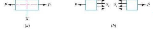
When a
body is subjected to two equal and opposite axial pulls P (also called tensile
load) as shown in Fig. (a), then the stress induced at any section of the body
is known as tensile stress as shown in Fig. (b). A little
consideration will show that due to the tensile load, there will be a decrease
in cross-sectional area and an increase in length of the body. The ratio of the
increase in length to the original length is known as tensile
strain.
Let P =
Axial tensile force acting on the body,
A =
Cross-sectional area of the body,
l =
Original length, and
δl =
Increase in length.
Tensile
stress, σt = P/A
Tensile strain, εt = δl / l
Compressive
Stress and Strain
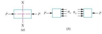
When a
body is subjected to two equal and opposite axial pushes P (also called
compressive load) as shown in Fig.(a), then the stress induced at any section
of the body is known as compressive stress as shown
in Fig.(b). A little consideration will show that due to the compressive
load, there will be an increase in cross-sectional area and a decrease in
length of the body. The ratio of the decrease in length to the original length
is known as compressive strain
Let P =
Axial compressive force acting on the body,
A =
Cross-sectional area of the body,
l =
Original length, and
δl =
Decrease in length.
Compressive
stress, σc = P/A
Compressive strain, εc = δl /l
Young's
Modulus or Modulus of Elasticity
Hooke's law states that when a material is
loaded within elastic limit, the stress is directly proportional to strain, i.e.
∝ ε
= E.ε
E
= σ / ε
=
P l / (A×δ l)
Where E
is a constant of proportionality known as Young's modulus or modulus of
elasticity. In S.I. units, it is usually expressed in GPa i.e.
GN/m2 or kN/mm2. It may be noted that Hooke's law holds
good for tension as well as compression.
Shear
Stress and Strain
When a
body is subjected to two equal and opposite forces acting tangentially across
the resisting section, as a result of which the body tends to shear off the
section, then the stress induced is called shear stress.
The
corresponding strain is known as shear strain and it is measured by the angular
deformation accompanying the shear stress. The shear stress and shear strain
are denoted by the Greek letters tau (τ) and phi (φ) respectively.
Mathematically,
Shear
stress, τ
=Tangential force / Resisting area
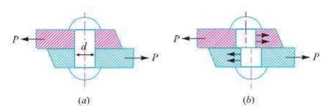
Consider
a body consisting of two plates connected by a rivet as shown in Fig. (a). In
this case, the tangential force P tends to shear off the rivet at one
cross-section as shown in Fig.(b). It may be noted that when the tangential
force is resisted by one cross-section of the rivet (or when shearing takes
place at one cross-section of the rivet), then the rivets are said to be in single
shear. In such a case, the area resisting the shear off the rivet,
A
= (π/4) × d2
and shear
stress on the rivet cross-section,
= P/A
=
(4P/ π d2)
Shear Modulus or Modulus of Rigidity
It has
been found experimentally that within the elastic limit, the shear stress is
directly proportional to shear strain. Mathematically
∝ φ
= C . φ
/ φ = C
where
τ = Shear
stress,
φ = Shear
strain, and
C = Constant
of proportionality, known as shear modulus or modulus of rigidity. It is also
denoted by N or G.
Working
Stress
When
designing machine parts, it is desirable to keep the stress lower than the
maximum or ultimate stress at which failure of the material takes place. This
stress is known as the working
stress
Factor
of Safety
It is defined, in general, as the ratio of the
maximum stress to the working stress. Mathematically,
Factor
of safety = Maximum stress / Working or design stress
In case of ductile materials e.g. mild steel, where the yield point is
clearly defined, the factor of safety is based upon the yield point stress. In
such cases,
Factor
of safety = Yield point stress / Working or design stress
In case
of brittle materials e.g. cast iron, the yield point is not well defined as for
ductile materials. Therefore, the factor of safety for brittle materials is
based on ultimate stress.
Factor
of safety = Ultimate stress / Working or design stress
This
relation may also be used for ductile materials
Poisson's
Ratio
It has
been found experimentally that when a body is stressed within elastic limit,
the lateral strain bears a constant ratio to the linear strain, Mathematically,
Lateral
strain / Linear strain = Constant
This
constant is known as Poisson's ratio and is
denoted by 1/m or µ.
Bulk
Modulus
When a
body is subjected to three mutually perpendicular stresses, of equal intensity,
then the ratio of the direct stress to the corresponding volumetric strain is known
as bulk
modulus. It is usually denoted by K. Mathematically, bulk modulus,
K
= Direct stress / Volumetric strain
Relation
Between Bulk Modulus and Young’s Modulus
The bulk
modulus (K) and Young's modulus (E) are related by the following relation,
E=
3K (1 - 2 µ)
Relation
Between Young’s Modulus and Modulus of Rigidity
The
Young's modulus (E) and modulus of rigidity (G) are related by the following
relation,
E=
2G (1 + µ)
Resilience
When a body is loaded within elastic limit, it
changes its dimensions and on the removal of the load, it regains its original
dimensions. So long as it remains loaded, it has stored energy in itself. On
removing the load, the energy stored is given off as in the case of a spring.
This energy, which is absorbed in a body when strained within elastic limit, is
known as strain energy. The strain energy is always capable of doing some
work.
The strain energy stored in a body due to external
loading, within elastic limit, is known as resilience and the maximum energy which can
be stored in a body up to the elastic limit is called proof
resilience. The proof resilience per unit volume of a material is known as modulus
of resilience.
It is an important property of a material and gives capacity of the
material to bear impact or shocks. Mathematically, strain energy stored in a
body due to tensile or compressive load or resilience,
U=
(σ2 ×V) / 2E
Modulus
of resilience = σ2 / 2E
where σ = Tensile or compressive stress, V = Volume
of the body, and
= Young's modulus of the material of the body
Torsional Shear Stress
When a
machine member is subjected to the action of two equal and opposite couples
acting in parallel planes (or torque or twisting moment), then the machine
member is said to be subjected to torsion. The stress set up by torsion is
known as torsional shear stress. It is zero at the centroidal
axis and maximum at the outer surface.
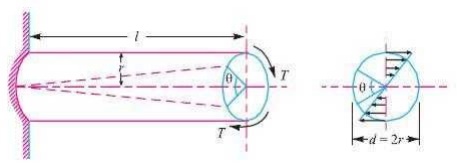
Consider a shaft fixed at one end and subjected to
a torque (T) at the other end as shown in Fig. As a result of this torque,
every cross-section of the shaft is subjected to torsional shear stress. We
have discussed above that the torsional shear stress is zero at the centroidal
axis and maximum at the outer surface. The maximum torsional shear stress at
the outer surface of the shaft may be obtained from the following equation:
(τ /r) = (T/J) = (Cθ/ l )
where
τ =
Torsional shear stress induced at the outer surface of the shaft or maximum
shear stress,
= Radius of the shaft,
= Torque
or twisting moment,
= Second
moment of area of the section about its polar axis or polar moment of inertia,
C =
Modulus of rigidity for the shaft material, l = Length of the shaft, and
= Angle of twist in radians on a length l.
Shafts
in Series and Parallel
When two
shafts of different diameters are connected together to form one shaft, it is
then known as composite shaft. If the
driving torque is applied at one end and the resisting torque at the other end,
then the shafts are said to be connected in series as shown in Fig. (a). In
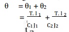
such cases, each shaft transmits the same torque and the total angle of twist
is equal to the sum of the angle of twists of the two shafts.
Mathematically,
total angle of twist,
If the
shafts are made of he same material,
then C1 = C2 = C.
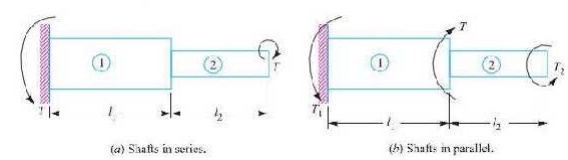
When the driving torque (T) is applied at the
junction of the two shafts, and the resisting torques T1 and T2 at the other
ends of the shafts, then the shafts are said to be connected in parallel, as
shown in Fig. 5.2 (b). In such cases, the angle of twist is same for both the
shafts,
i.e.
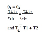
If the
shafts are made of the same material, then C1 = C2.
Bending
Stress in Straight Beams
In
engineering practice, the machine parts of structural members may be subjected
to static or dynamic loads which cause bending stress in the sections besides
other types of stresses such as tensile, compressive and shearing stresses.
Consider a straight beam subjected to a bending moment M as shown in Fig. The
following assumptions are usually made while deriving the bending formula.
The material of the beam is perfectly homogeneous
(i.e. of the same material throughout) and isotropic (i.e. of equal elastic
properties in all directions).
The material of the beam obeys Hooke’s law.
The transverse sections (i.e. BC or GH) which were
plane before bending, remain plane after bending also.
Each layer of the beam is free to expand or
contract, independently, of the layer, above or below it.
The Young’s modulus (E) is the same in tension and
compression.
The loads are applied in the plane of bending.
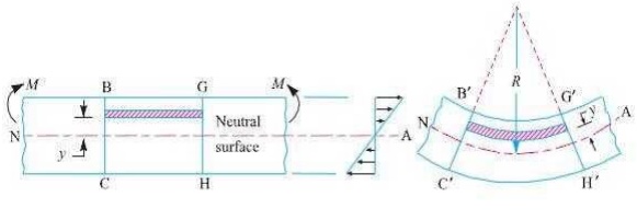
A little consideration will show that when a beam is subjected to the bending moment, the fibres on the upper side of the beam will be shortened due to compression and those on the lower side will be elongated due to tension. It may be seen that somewhere between the top and bottom fibres there is a surface at which the fibres are neither shortened nor lengthened. Such a surface is called neutral surface. The intersection of the neutral surface with any normal cross-section of the beam is known as neutral axis. The stress distri bution of a beam is shown in Fig. The bending equation is given by
where M = Bending moment acting at the given
section, σ = Bending stress,
I =
Moment of inertia of the cross-section about the neutral axis, y = Distance
from the neutral axis to the extreme fibre,
E =
Young’s modulus of the material of the beam, and R = Radius of curvature of the
beam.
Related Topics