Chapter: Mechanical : Design of Machine Elements : Steady Stresses and Variable Stresses In Machine Members
Shafts in Series and Parallel
Shafts in Series and Parallel
When two shafts of different diameters are connected together to form one shaft, it is then known as composite shaft. If the driving torque is applied at one end and the resisting torque at the other end, then the shafts are said to be connected in series as shown in Fig. (a). In such cases, each shaft transmits the same torque and the total angle of twist is equal to the sum of the angle of twists of the two shafts.
Mathematically, total angle of twist,
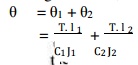
If the shafts are made of he same material, then C1 = C2 = C.
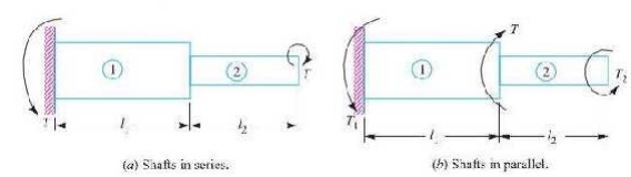
When the driving torque (T) is applied at the junction of the two shafts, and the resisting torques T1 and T2 at the other ends of the shafts, then the shafts are said to be connected in parallel, as shown in Fig. 5.2 (b). In such cases, the angle of twist is same for both the shafts,
i.e.
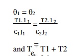
If the shafts are made of the same material, then C1 = C2.
Bending Stress in Straight Beams
In engineering practice, the machine parts of structural members may be subjected to static or dynamic loads which cause bending stress in the sections besides other types of stresses such as tensile, compressive and shearing stresses. Consider a straight beam subjected to a bending moment M as shown in Fig. The following assumptions are usually made while deriving the bending formula.
The material of the beam is perfectly homogeneous (i.e. of the same material throughout) and isotropic (i.e. of equal elastic properties in all directions).
The material of the beam obeys Hooke’s law.
The transverse sections (i.e. BC or GH) which were plane before bending, remain plane after bending also.
Each layer of the beam is free to expand or contract, independently, of the layer, above or below it.
The Young’s modulus (E) is the same in tension and compression.
The loads are applied in the plane of bending.
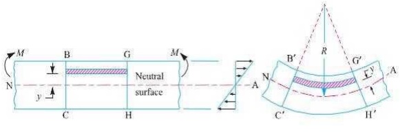
A little consideration will show that when a beam is subjected to the bending moment, the fibres on the upper side of the beam will be shortened due to compression and those on the lower side will be elongated due to tension. It may be seen that somewhere between the top and bottom fibres there is a surface at which the fibres are neither shortened nor lengthened. Such a surface is called neutral surface. The intersection of the neutral surface with any normal cross-section of the beam is known as neutral axis. The stress distri bution of a beam is shown in Fig. The bending equation is given by
where M = Bending moment acting at the given section, σ = Bending stress,
I = Moment of inertia of the cross-section about the neutral axis, y = Distance from the neutral axis to the extreme fibre,
E = Young’s modulus of the material of the beam, and R = Radius of curvature of the beam.
Related Topics