Chapter: Aquaculture Engineering : Removal of Particles
Settling or gravity filters - Methods for particle removal in fish farming
Settling or gravity filters
Settling basing
Settling is a simple method for removing particles from the water. The principle utilized is that particles have a higher relative density than water (1.005–1.2 compared to 1 for freshwater), so they will sink. This phenomenon can easily be observed when water containing suspended parti-cles is allowed to stand for a period. A natural sep-aration process will occur and the particles will sink to the bottom. The difference in relative density between the particles and the water controls the velocity of the separation process.
For small particles (0.1–1 mm) and unobstructed settling, the sinking velocity of the particles is given by Stoke’s law:
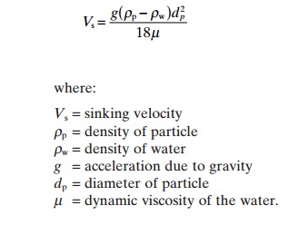
This also demonstrates why the particles with the highest density are the simplest to remove.
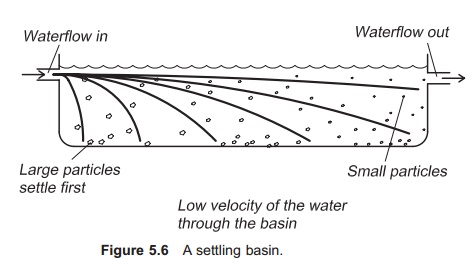
The simplest way to utilize gravitational force for separation is to send the effluent water through a basin with a large surface area where the water velocity is reduced: separation will then occur in the basin provided that the sinking velocity of the par-ticle created by the gravitational force does not exceed the horizontal velocity component created by the water flow through the basin (Fig. 5.6), in which case the particle will flow out of the basin in the water. The following equation can be set up to achieve settling:
Vs> Q/A
Where:
Vs=sinking velocity of the particle (m/h)
A =surface area of the basin (m2)
Q =water flow through the basin (m3/h)
The relation Q/A is called the surface load or over-flow rate for the settling basin. Because difference in density between water and faeces is small quite a long hydraulic residence time is required. In fish farming the normal surface load is between 1 and
Example
A water flow of 1000 l/min (60 m3/h) is to be purified by the use of a settling basin. Determine the size and design of the basin.
Expect a surface load of 3 m/h
Vs> Q/A
A > Q/Vs
> 60 m3/h /3 m/h
> 20 m2
This means that the surface area of the pond needs to be more than 20 m2 to allow proper settling. If a width : length ratio of 1 : 3 is chosen for the basin, this means that the exterior measurements of the basin will be about 2.6 m × 7.7 m. Two settling basins are needed so that one can be running while purification and sludge removal can be done in the other.
Other designs of settling basin take account of hydraulic retention time (t) or mean fluid velocity (vm).
t = V/Q
vm= L/t= Q/Acs
where:
V =volume of the settling basin
L =length of settling basin
Acs=cross-sectional area of the basin.
Reported values for retention times are 15–40 min, while recommended mean fluid velocities are in the range 1–4 m/min.
The flow pattern in a settling basin used in fish farming is normally horizontal. However, it is also possible to use settling with a vertical flow pattern. Such filters will have a tower like design. Water flows slowly upwards and because of the gravita-tional forces the particles will sink with a greater velocity. Specially designed filters, such as the lamella separation filter are used to improve set-tling conditions, and also the investment require-ments. Sending the water over biofilm can improve the settling and filtration efficiency. Small particleswill be attracted to and settle on the biofilm.Addi-tion of polymers or other chemicals before settling can be used to increase the particle size by floccu-lation, and this also removes smaller particles, pos-sibly in the settling basin.
The great disadvantage with settling basins is that the settled particles remain lying in the water flow, so there is a possibility that nutrients will leak from the particles, especially phosphorus which is weakly attached to the particles.2,4 Additionally, resuspen-sion of settled particles into the water may occur, even if particles are regularly removed from the basin; for this reason there must be adequate depth in the settling basin. Continuous removal of settled particles from the basin is impossible from a cost perspective. The removal of settled particles must, however, be carried out regularly to optimize basin function. This can be done by various methods, for instance by using a vacuum pump. It is important that mixing of sludge and water is kept to a minimum to avoid resuspension of particles with the result that the nutrients go directly to the outlet. It is quite common to have two settling basins, so that one can be used while the other is purified.
Compared to using a micro strainer, settling basins require a much greater area and this can be a disadvantage. However, if the surroundings and ground conditions are suitable, settling basins are simple and cheap to construct.
Results from testing shows reduced removal rates with small particles. It is quite difficult to remove particles smaller than 100 μm using a set-tling basin.27 Inlet values of less than 10 mg TSS per litre are difficult to treat, and those below 6 mg TSS per litre are also difficult to obtain. To process values in this range special methods must be used, such as addition of polymers or use of biofilm to attract particles.
Swirl separators, hydrocyclones
In a swirl separator or a hydrocyclone the principle that the particles are more dense than water is also used, but here centrifugal forces are used in addi-tion to increase this difference. To illustrate this, the water inside a cup can be rotated and the par-ticles will be hurled out towards the edges (Fig. 5.7). This is also the reason why this filter is sometimes called a tea-cup settler. In a swirl separator the water enters along the periphery of a circular tank,
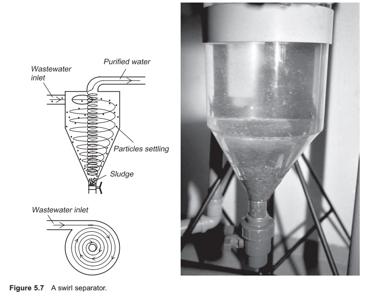
so the particles follow the periphery and the puri-fied water will be pressed into the centre. The par-ticles will then sink to the bottom, while the purified water is drained out of the centre. Because the cen-trifugal forces are greater than the gravitational force, a smaller area is needed than for a traditional settling basin to remove the same amount of particles. Re-suspension or leakage is also less than with a settling basin, because the area where this occurs is smaller. However, in comparison to the settling basin, the hydraulic load on a swirl separa-tor may be much higher, 20–25 m/h.24 An advantage of this type of filter unit is its quite simple construction with no movable parts; in addi-tion is it cheap to buy and area intensive. The great disadvantage with swirl separators is that they require uniform water flow for optimal efficiency. If the flow is higher than the filter is designed for, the particles will flow out of the unit with the outlet water in the center.
Example
An outlet water flow of 10 l/min (0.6 m3/h) is to be purified using a swirl separator. The acceptable hydraulic load is set to 20 m/h. Find the necessary size of the separator.
Vs> Q/A A> Q/Vs
> 0.60 m3 /h 20 m/h
> 0.03 m2
The radius of the separator must be more than 9.8 cm.
Related Topics