Chapter: Digital Principles and System Design : Asynchronous Sequential Circuits
Reduction of State and Flow Tables
REDUCTION OF STATE AND
FLOW TABLES
The procedure for reducing the
number of internal states in an asynchronous sequential circuit resembles the
procedure that is used for synchronous circuits.
ü Implication Table and Implied State
The state-reduction procedure for completely
specified state tables is based on an algorithm that combines two slates in a
slate table into one as long as they can be shown to be equivalent. Two states
are equivalent if, for each possible input, they give exactly the same output
and go to the same next states or to equivalent next states.
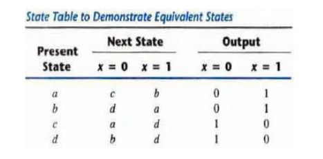
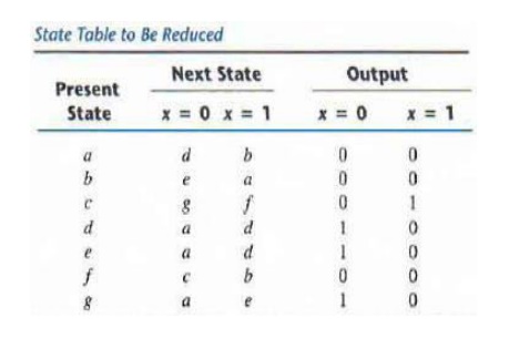
Consider for example the state table shown in
above table. The present states a and b have the same output for the same
input. Their next states are c and d for x = 0 and b and a for x = 1. If we can
show that the pair of states (c, d) are equivalent, then the pair of states (a
, b) will also be equivalent, because they will have the same or equivalent
next states. When this relationship exists, we say that (a. b) imply (c, d) in
the sense that if a and b are equivalent then r and d have to be equivalent.
Similarly, from the last two rows of above table, we find that the pair of
stales (c, d) implies the pair of states (a, b). The characteristic of equivalent
states is that if (a, b) imply (c, d) and (c, d) imply (a, b), then both pairs
of states are equivalent that is, a and b are equivalent, and so are c and d.
As a consequence, the four rows of table can be reduced to two rows by
combining a and b into one state and c and d into a second state.
The implication table is shown in Fig. On the left
side along the vertical are listed all the states defined in the state table
except the first and across the bottom horizontally are listed all the states
except the last. The result is a display of all possible combinations of two
stares with a square placed in the intersection of a row and a column where the
two states can be tested for equivalence. Two states having different outputs
for the same input are not equivalent.
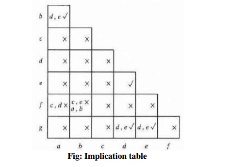
Two states that are not equivalent are marked with
a cross [X] in the corresponding square whereas their equivalence is recorded
with a check mark(‘Dik’). Some of the squares have entries of implied states that
must be investigated further to determine whether they are equivalent. Thus
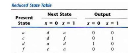
table can be reduced from seven states to four one for each member of the
preceding partition. The reduced state table is obtained by replacing state b
by a and states e and g by d and it is shown below,
ü
Merging of the Flow Table
Incompletely specified states can
be combined to reduce the number of state in the flow table. Such stares cannot
be called equivalent because the formal definition of equivalence requires that
all outputs and next states be specified for all inputs. Instead, two
incompletely specified states that can be combined are said to be Compatible.
The process that must be applied in order to find a suitable group of
compatibles for the purpose of merging a flow table can be divided into three
steps:
1.
Determine all compatible pairs by using the
implication table.
2.
Find the maximal compatibles with the use of a
merge r diagram.
3.
Find a minimal collection of compatibles that
covers all the states and is closed.
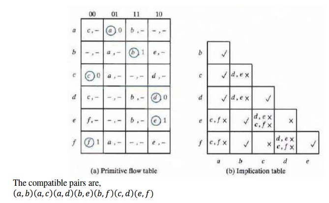
ü Compatible
Pairs-The entries in each square of primitive flow table represent
the next state and
output The dashes represent the unspecified states or outputs. The implication
table is used to fmd compatible states just as it is used to find equivalent
stales in the completely specified case. The only difference is that, when
comparing rows, we are at liberty to adjust the dashes to fit any desired
condition.
ü
Maximal Compatibles
The maximal compatible is a group of
compatibles that contains all the possible combinations of compatible states.
The maximal compatible can be obtained from a merger diagram. The merger
diagram is a graph in which each state is represented by a dot placed along the
circumference of a circle. Lines are drawn between any two corresponding dots
that form a compatible pair. All possible compatibles can be obtained from the
merger diagram by observing the geometrical patterns in which states are
connected to each other. An isolated dot represents a state that is not
compatible with any other state. A line represents a compatible pair. A
triangle constitutes a compatible with three states.
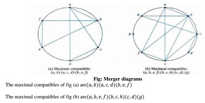
The maximal compatibles of fig (a) are
The maximal compatibles of fig (b) are
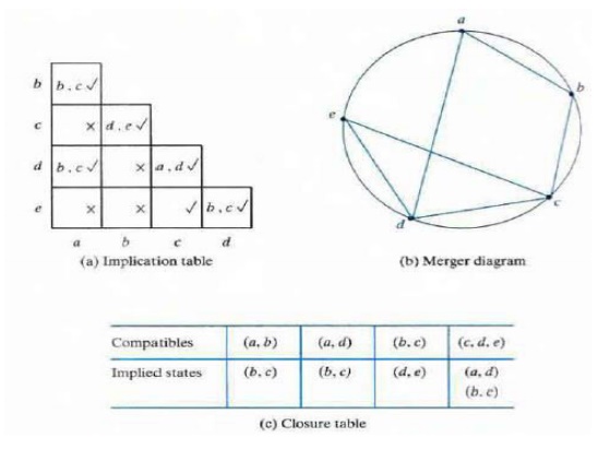
Closed-Covering Condition
The condition that must be
satisfied for merging rows is that the set of chosen compatibles must cover
all the states and must be closed. The set will cover all the states if
it includes all the states of the original state table. The closure condition
is satisfied if there are no implied states or if the implied states are
included within the set. A closed set of compatibles that covers all the states
is called a closed covering.
Example:
Related Topics