Chapter: Civil : Railway Airport Harbour Engineering : Railway Engineering : Points and Crossings
Railway Engineering: Switches
Switches
A set of
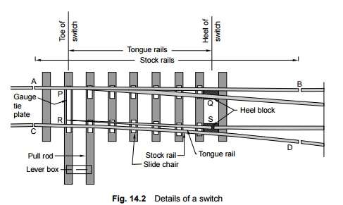
points or switches consists of the following main constituents (Fig. 14.2).
(a) A pair of
stock rails, AB and CD, made of medium-manganese steel.
(b) A pair of
tongue rails, PQ and RS, also known as switch rails, made of medium-manganese
steel to withstand wear. The tongue rails are machined to a very thin section
to obtain a snug fit with the stock rail. The tapered end of the tongue rail is
called the toe and the thicker end is called the heel.
(c) A pair of
heel blocks which hold the heel of the tongue rails is held at the standard
clearance or distance from the stock rails.
(d) A number of
slide chairs to support the tongue rail and enable its movement towards or away
from the stock rail.
(e) Two or
more stretcher bars connecting both the tongue rails close to the toe, for the
purpose of holding them at a fixed distance from each other.
(f) A gauge
tie plate to fix gauges and ensure correct gauge at the points.
1.Types of Switches
Switches are of two types,
namely, stud switch and split switch. In a stud type of switch,
no separate tongue rail is provided and some portion of the track is moved from
one side to the other side. Stud switches are no more in use on Indian
Railways. They have been replaced by split switches. These consist of a pair of
stock rails and a pair of tongue rails. Split switches may again be of two
types-loose heel type and fixed heel type. These are discussed below.
Loose heel type In this
type of split switch, the switch or tongue rail finishes at the heel of
the switch to enable movement of the free end of the tongue rail. The fish
plates holding the tongue rail may be straight or slightly bent. The tongue
rail is fastened to the stock rail with the help of a fishing fit block and
four bolts. All the fish bolts in the lead rail are tightened while those in
the tongue rail are kept loose or snug to allow free movement of the tongue. As
the discontinuity of the track at the heel is a weakness in the structure, the
use of these switches is not preferred.
Fixed heel type In this
type of split switch, the tongue rail does not end at the heel of the
switch but extends further and is rigidly connected. The movement at the toe of
the switch is made possible on account of the flexibility of the tongue rail.
Toe of switches
The toe of the switches may be of the following types.
Undercut
switch In this switch the foot of the stock rail is planed to
accommodate the tongue rail (Fig. 14.3).
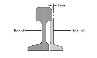
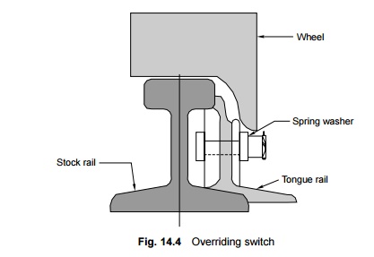
Overriding
switch In this case, the stock rail occupies the full section and the
tongue rail is planed to a 6-mm (0.25") -thick edge, which overrides
the foot of the stock rail (Fig. 14.4). The switch rail is kept 6 mm
(0.25") higher than the stock rail from the heel to the point towards the
toe where the planing starts. This is done to eliminate the possibility of
splitting caused by any false flange moving in the trailing direction. This
design is considered to be an economical and superior design due to the reasons
given below.
(a) Since the
stock rail is uncut, it is much stronger.
(b) Manufacturing
work is confined only to the tongue rail, which is very economical.
(c) Although
the tongue rail has a thin edge of only 6 mm (0.25"), it is supported by
the stock rail for the entire weakened portion of its length. As such, the combined strength of the rails between the
sleepers is greater than that of the tongue rail alone in the undercut switch.
Overriding switches have been standardized on the Indian
Railways.
2 Important Terms Pertaining to Switches
The following terms are common when discussing the design of
switches.
Switch angle This is
the angle between the gauge face of the stock rail and that of the
tongue rail at the theoretical toe of the switch in its closed position. It is
a function of the heel divergence and the length of the tongue rail.
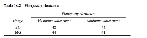
Flangeway
clearance This is the distance between the adjoining faces of the running
rail and the check rail/wing rail at the nose of the crossing. It is meant for
providing a free passage to wheel flanges. Table 14.2 gives the minimum and
maximum values of flangeway clearance for BG and MG tracks.
Heel divergence This is
the distance between the gauge faces of the stock rail and the tongue
rail at the heel of the switch. It is made up of the flangeway clearance and
the width of the tongue rail head that lies at the heel.
Throw of the switch This is
the distance through which the tongue rail moves laterally at the toe of
the switch to allow movement of the trains. Its limiting values are 95-115 mm
for BG routes and 89-100 mm for MG routes.
Related Topics