Chapter: Electrical machines : DC Motor
Principle of operation of a D.C. Motor
Principle of operation of a D.C. Motor
The principle of operation of a d.c. motor can be stated in a single statement as ŌĆśwhen a current carrying conductor is placed in a magnetic field; it experiences a mechanical forceŌĆÖ. In a practical d.c. motor, field winding produces a required magnetic field while armature conductors play a role of a current carrying conductors and hence armature conductors experience a force. As conductors are placed in the slots which are on the periphery, the individual force experienced by the conductors acts as a twisting or turning force on the armature which is called a torque. The torque is the product of force and the radius at which this force acts. So overall armature experiences a torque and starts rotating. Let us study this motoring action in detail.
Consider a single conductor placed in a magnetic field as shown in the Fig. 8.1(a). The magnetic field is produced by a permanent magnet but in a practical d.c. motor it is produced by the field winding when it carries a current.
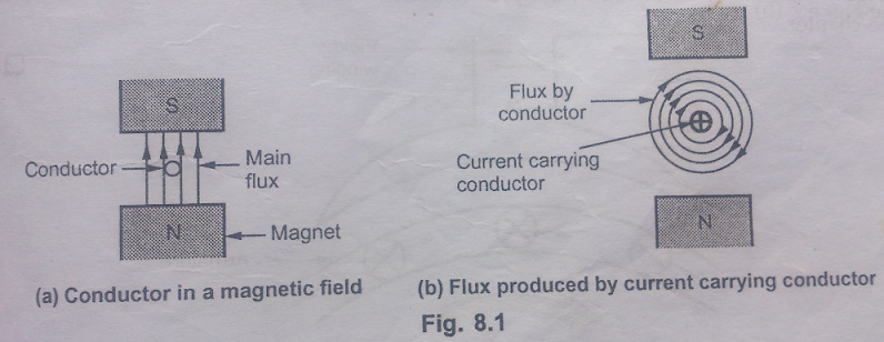
Now this conductor is excited by a separate supply so that it carries a current in a particular direction. Consider that it carries a current away from an observer as shown in the fig. 8.1(b). Any current carrying conductor produces its own magnetic field around it, hence this conductor also produces its own flux, around. The direction of this flux can be determined by right hand thumb rule. For direction of current considered, the direction of flux around a conductor is clockwise. For simplicity of understanding, the main flux produced by the permanent magnet is not shown in the Fig. 8.1(b).
Now there are two fluxes present,
1. The lux produced by the permanent magnet called main flux.
2. The lux produced by the current carrying conductor.
These are shown in the fig.8.2(a). From this, it is clear that on one side of the conductor, both the fluxes are in the same direction. In this case, on the left of the conductor there is gathering of the flux lines as two fluxes help each other. As against this, on the right of the conductor, the two fluxes are in opposite direction and hence try to cancel each other. Due to this, the density of the flux lines in this area gets weakened. So on the left, there exists high flux density area while on the right of the conductor there exists low flux density area as shown in the Fig. 8.2(b).
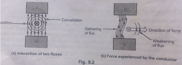
This flux distribution around the conductor acts like a stretched rubber band under tension. This exerts a mechanical force on the conductor which acts from high flux density area towards low flux density area, i.e, from left to right or the case considered as shown in the fig.8.2(b)
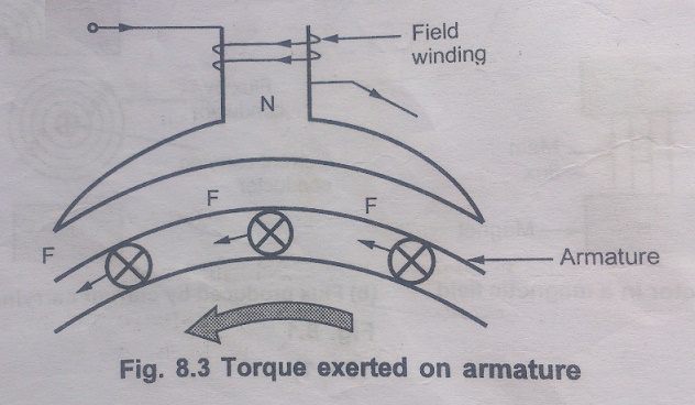
In the practical d.c. motor, the permanent magnet is replaced by a field winding which produces the required flux called main flux and all the armature conductors, mounted on the periphery of the armature drum, get subjected to the mechanical force. Due to this, overall armature experiences a twisting force called torque and armature of the motor starting rotating.
Direction of Rotation of Motor
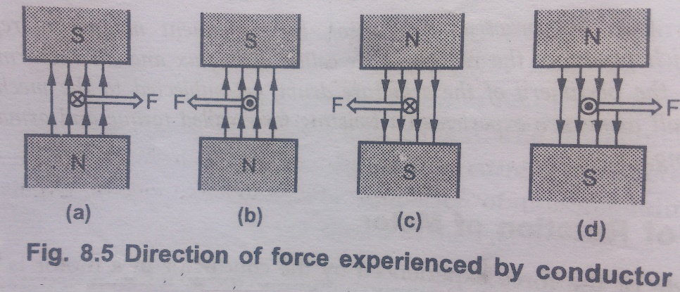
The magnetic of the force experienced by the conductor in a motor is given by,
F = BlI newtons (N)
B = Flux density due to the flux produced by the field winding
l = Active length of the conductor
I = Magnitude of the current passing through the conductor
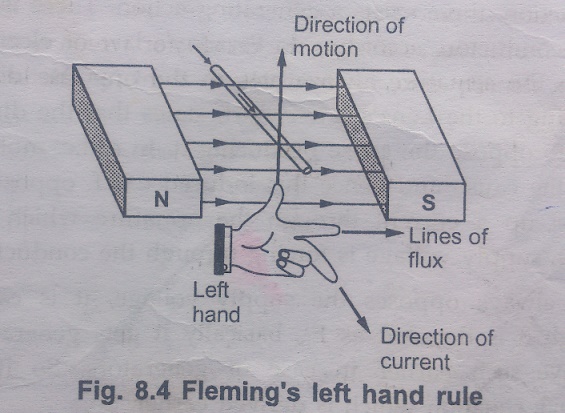
The direction of such force i.e., the direction of rotation of a motor can be determined by FlemingŌĆÖs left hand rule. So FlemingŌĆÖs right hand rule is to determine direction of induced e.m.f. i.e., for generating action while FlemingŌĆÖs left hand rule is to determine direction of force experienced i.e. for motoring action.
D.C. Motor Principle
A machine that converts d.c. power into mechanical power is known as a d.c.motor. Its operation is based on the principle that when a current carrying conductor is placed in a magnetic field, the conductor experiences a mechanical force.
The direction of this force is given by FlemingŌĆÖs left hand rule and magnitude is given by;
F = BlI newtons (N)
B = Flux density due to the flux produced by the field winding
l = Active length of the conductor
I = Magnitude of the current passing through the conductor
Basically, there is no constructional difference between a d.c. motor and a d.c.generator. The same d.c. machine can be run as a generator or motor.
Related Topics