Chapter: Power Electronics : Power Semi Conductor Devices
Power diode
Power diode:
Diode is a two terminal P-N junction semiconductor device, with terminals anode (A) and cathode (C).
Symbol:
The symbol of the Power diode is same as signal level diode.

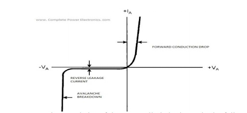
If terminal A experiences a higher potential compared to terminal K, the device is said to be forward biased and a forward current will flow from anode to cathode. This causes a small voltage drop across the device (<1V) called as forward voltage drop(Vf), which under ideal conditions is usually ignored. By contrast, when a diode is reverse biased, it does not conduct and the diode then experiences a small current flowing in the reverse direction called the leakage current. It is shown below in the VI characteristics of the diode.
The Structure of Power Diode is different from the low power signal diode.
1. Power Diode Characteristics:
The reverse recovery characteristics of the Power diode is shown in the following figure. From the figure, we can understand the turn off characteristic of the diode. The Reverse recovery time tRR is the time interval between the application of reverse voltage and the reverse current dropped to 0.25 of IRR.
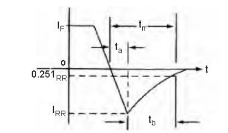
Parameter ta is the interval between the zero crossing of the diode current to it reaches IRR. Parameter tb is the time interval from the maximum reverse recovery current to
0:25 of IRR .
The lower trr means fast diode switching. The ratio of the two parameters ta and tb is known as the softness factor SF.
Datasheet Parameters:
For power diodes, a data sheet will give two voltage ratings. One is the repetitive peak inverse voltage (VRRM) and the other is the non repetitive peak inverse voltage. The non repetitive voltage (VRM) is the diode‟s capability to block a reverse voltage that may occur occasionally due to over voltage surge. The data sheet of a diode normally specifies three different current ratings. They are: (1) Average current; (2) RMS current; and (3) Peak current. A design engineer must ensure that each of these values are never exceeded.
2. Diode Selection:
A power diode is chosen primarily based on forward current (IF ) and the peak inverse (VRRM) voltage.
3. Diode Protection:
Snubber circuits are essential for diodes used in switching circuits. It can save a diode from overvoltage spikes, which may arise during the reverse recovery process. A very common snubber circuit for a power diode consists of a capacitor and a resistor connected in parallel with the diode
4. Power Diode Applications:
As a rectifier Diode
For Voltage Clamping
As a Voltage Multiplier
As a freewheeling Diode
5. Types of Power Diode:
Schottky diodes:
These diodes are used where a low forward voltage drop (usually 0.3V) is needed in low output voltage circuits. These diodes are limited in their blocking voltage capabilities to 50 – 100V.
Fast Recovery diodes:
These are used in high frequency circuits in combination with controllable switches where a small reverse recovery time is needed. At power levels of several hundred volts and several hundred amperes, these diodes have trr ratings of less than a few microsecond.
Line – frequency diodes:
The on state voltage of these diodes is designed to be as low as possible and as a consequence have larger trr, which are acceptable for line frequency applications. These diodes are available with blocking voltage ratings of several kilovolts and current ratings of several kilo amperes. Moreover, they can be connected in series and parallel to satisfy any voltage and current requirement.
How to test Diode?
We know that fact that resistance of diode in forward biased condition is low and the resistance of diode in reverse biased condition is high. Keep the multimeter in the ohmmeter section. If we measure the resistance of a diode using the connections like red lead to anode and black lead(common) to cathode, a healthy forward biased diode will give low resistance. A high resistance reading in both directions indicates an open(defective device) condition, while a very low resistance reading in both directions will probably indicate a shorted device.
Related Topics