Chapter: Civil : Mechanics Of Fluids : Fluid Properties And Fluid Statics
Pascal s Law
Pascal's Law
This law states:
The pressure at a point in a fluid at rest is the same in all directions.
To show this, we will consider a very small wedge of fluid surrounding the point. This wedge is unit thickness into the page:
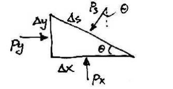
As with all static objects the forces in the x and y directions should balance. Hence:
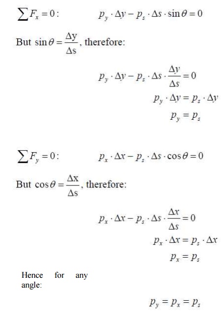
And so the pressure at a point is the same in any direction. Note that we neglected the weight of the small wedge of fluid because it is infinitesimally small. This is why Pascal's Law is restricted to the pressure at a point.
Pressure Variation with Depth
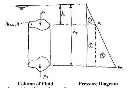
Pressure in a static fluid does not change in the horizontal direction as the horizontal forces balance each other out. However, pressure in a static fluid does change with depth, due to the extra weight of fluid on top of a layer as we move down wards. Consider a column of fluid of arbitrary cross section of area, A:
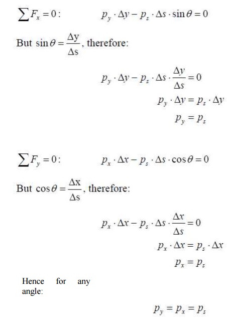
Considering the weight of the column of water, we have:

This difference in pressure varies linearly in h, as shown by the Area 3 of the pressure diagram. If we let h1 = 0 and consider a gauge pressure, then p1 = 0 and we have:

Where h remains the height of the column. For the fluid on top of the column, this isthe source of 1 p and is shown as Area 1 of the pressure diagram. Area 2 of thepressure diagram is this same pressure carried downwards, to which is added more pressure due to the extra fluid.
The gauge pressure at any depth from the surface of a fluid is:

Summary
1. Pressure acts normal to any surface in a static fluid;
2. Pressure is the same at a point in a fluid and acts in all directions;
3. Pressure varies linearly with depth in a
fluid.
By applying these rules to a simple swimming pool, the pressure distribution around the edges is as shown:

Note:
1. Along the bottom the pressure is constant due to a constant depth;
2. Along the vertical wall the pressure varies linearly with depth and acts in the horizontal direction;
3. Along the sloped wall the pressure again varies linearly with depth but also acts normal to the surface;
4. At the junctions of the walls and the bottom the pressure is the
same.
Problems - Pressure
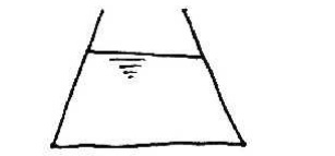
1. Sketch the pressure distribution applied to the container by the fluid:
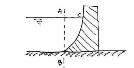
2. For the dam shown, sketch the pressure distribution on line AB and on the surface of the dam, BC. Sketch the resultant force on the dam.
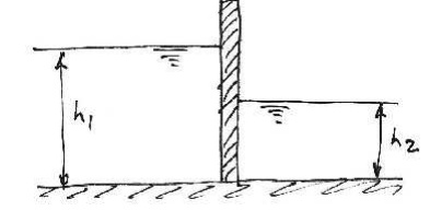
3. For the canal gate shown, sketch the pressure distributions applied to it. Sketch the resultant force on the gate? If h1 = 6.0 m and h2 = 4.0 m, sketch the pressure distribution to the gate. Also, what is the value of the resultant force on the gate and at what height above the bottom of the gate is it applied
Pressure Head
Pressure in fluids may arise from many sources, for example pumps, gravity, momentum etc.
Since p = ?gh, a height of liquid column can be associated with thepressure p arising from such sources. This height, h, is known as the pressure head.
Example:
The gauge pressure in a water mains is 50 kN/m2, what is the pressure head? The pressure head equivalent to the pressure in the pipe is just:
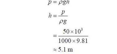
So the pressure at the bottom of a 5.1 m deep swimming pool is the same as the pressure
in this pipe.
Manometers
A manometer (or liquid gauge) is a pressure measurement device which uses relationship
between pressure and head to give readings.
In the following, we wish to measure the pressure of a fluid in a pipe.
Piezometer
This is the simplest gauge. A small vertical tube is connected to the pipe and its top is left open to the atmosphere, as shown.
The pressure at A is equal to the pressure due to the column of liquid of height h1 : Similarly,
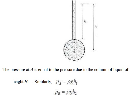
The problem with this type of gauge is that for usual civil engineering applications the pressure is large (e.g. 100 kN/m2) and so the height of the column is impractical(e.g.10 m). Also, obviously, such a gauge is useless for measuring gas pressures.
U-tube Manometer
To overcome the problems with the piezometer, the U-tube manometer seals the fluid by
using a measuring (manometric) liquid:
Choosing the line BC as the interface between the measuring liquid and the fluid, we

know: For the left-hand side of the U-tube:

For the right hand side:

Where we have ignored atmospheric pressure and are thus dealing with gauge pressures. Thus:

Notice that we have used the fact that in any continuous fluid, the pressure is the same at any horizontal level.
Differential Manometer
To measure the pressure difference between two points we use a u-tube as shown:
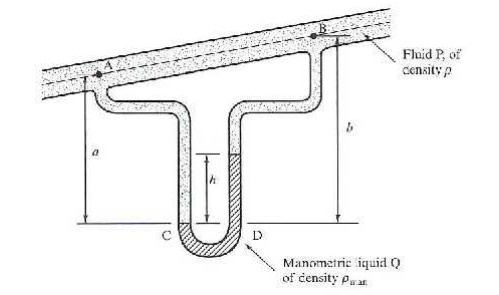
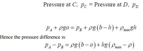
Using the same approach as before:
PROBLEM 8
A U-Tube manometer is used to measure the pressure of water in a pipe line, which is in excess of atmospheric pressure. The right limb of the manometer contains water and mercury is in the left limb. Determine the pressure of water in the main line, if the difference in level of mercury in the limbs U. U tube is 10 cm and the free surface of mercury is in level with over the centre of the pipe. If the pressure of water in pipe line is reduced to 9810 N/m2, Calculate the new difference in the level of mercury. Sketch the arrangement in both cases.
Given,
Difference of mercury = 10 cm = 0.1 m.
Let PA = pr of water in pipe line (ie, at point A)
The point B and C lie on the same horizontal line. Hence pressure at B should be equal to pressure at C.
But pressure at B = Pressure at A and Pressure due to 10 cm (or) 0.1m of water.
=PA +p ´g ´h
where , P = 1000kg/m3 and h = 0.1 m
=PA +1000 ´9.81´0.1
=PA +981N / m 2 (i)
Pressure at C = Pressure at D + pressure due to 10 cm of mercury
0 +P0 ´g ´h0
where po for mercury =13.6 ´1000kg / m3
h0 = 10 cm = 0.1 m
Pressure at C =0 +(13.6 ´1000)´9.81´0.1
= 13341.6 N (ii)
But pressure at B is = to pr @ c. Hence,
equating (i) and (ii)
PA +981 =13341.6
PA =13341.6 -981 =12360.6N / m 2
II part:
Given p A =9810N / m 2
In this case the pressure at A is 9810 N/m2 which is less than the 12360.6 N/m2. Hence the mercury in left limb will rise. The rise of mercury in left limb will be equal to the fall of mercury in right limb as the total volume of mercury remains same.
Let, x = Ries of mercury in left limb in cm
Then fall of mercury in right limb = x cm.
The points B, C and D show the initial condition.
The pressure at B * = pressure at C*
Pressure at A + pressure due to (10-x) cm of water.
Whereas points B*, C*, and D* show the final conditions.
= pressure at D* + pressure due to (10-2x) cm of mercury.
(or)
PA +p1 g ´h1 =pD * +p 2 ´g ´h2
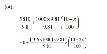
Dividing by 9.81 , we get,
1000 +100 -10x =1360 -272x
272x -10x =1360 -1100
262 x = 260
X=0.992cm
\ New difference of mercury = 10 - 2 x cm
![]()
=10 -2 ´0.992
= 8.016 cm.
PROBLEM 9
A differential manometer is connected at the two points A and B of two pipes a shown in figure. The pipe A contains a liquid of sp. Gr = 1.5 while pipe b contains a liquid of sp . gr = 0.9 . The pressures at A and B are 1 kgf / cm2 respectively. Find the difference in mercury level in the differential manometer.
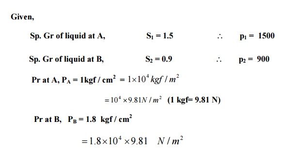
Density of mercury =13.6 ´1000kg / m 3
Pr above X - X in left limb = 13.6 ´1000 ´9.81´h +1500 ´9.81´(2+3)+PA
=13.6 ´1000 ´9.81´h +7500 ´9.81´10 4
Pr above X - X in the right limb =900 ´9.81´(h+2)+PB
=900´9.81´(h+2)+1.8´104 ´9.81
Equating two pressure, we get,
13.6 ´1000 ´9.81h +7500 ´93.81 +9.81´10 4
=900´9.81´(h+2)+1.8´104 ´9.81
Dividing by 1000 ´9.81, we get
13.6h +7.5 +10 =(h+2.0)´0.9 +18
13.6h +17.5 =0.9h +1.8 +18 =0.9h +19.8
(13.6 -0.9)h=19.8 -17.5 or 12.7 h = 2.3
h =0.181m =18.1cm
Related Topics