Chapter: High Voltage Engineering : Over Voltages in Electrical Power Systems
Over voltage Protection
Over voltage Protection
The causes of over voltages in the system have been studied extensively in previous sections. Basically, there are two sources: (i) external over voltages due to mainly lightning, and (ii) internal overvoltage mainly due to switching operation. The system can be protected against external over voltages using what are known as shielding methods which do not allow an arc path to form between the line conductors and ground, thereby giving inherent protection in the line design. For protection against internal voltages normally non-shielding methods are used which allow an arc path between the ground structure and the line conductor but means are provided to quench the arc. The use of ground wire is a shielding method whereas the use of spark gaps, and lightning arresters are the non-shielding methods. We will study first the non-shielding methods and then the shielding methods. However, the non shielding methods can also be used for external over voltages.
The non-shielding methods are based upon the principle of insulation breakdown as the Overvoltage is incident on the protective device; thereby a part of the energy content in the overvoltage is discharged to the ground through the protective device. The insulation breakdown is not only a function of voltage but it depends upon the time for which it is applied and also it depends upon the shape and size of the electrodes used.
The steeper the shape of the voltage wave, the larger will be the magnitude of voltage required for breakdown; this is because an expenditure of energy is required for the rupture of any dielectric, whether gaseous, liquid or solid, and energy involves time. The energy criterion for various insulations can be compared in terms of a common term known as Impulse Ratio which is defined as the ratio of breakdown voltage due to an impulse of specified shape to the breakdown voltage at power frequency. The impulse ratio for sphere gap is unity because this gap has a fairly uniform field and the breakdown takes place on the field ionization phenomenon mainly whereas for a needle gap it varies between 1.5 to 2.3 depending upon the frequency and gap length. This ratio is higher than unity because of the non-uniform field between the electrodes.
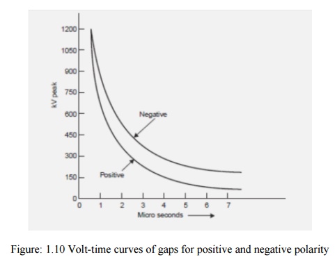
The impulse ratio of a gap of given geometry and dimension is greater with solid than with air dielectric. The insulators should have a high impulse ratio for an economic design whereas the lightning arresters should have a low impulse ratio so that a surge incident on the lightning arrester may be-by passed to the ground instead of passing it on to the apparatus. The volt-time characteristics of gaps having one electrode grounded depend upon the polarity of the voltage wave. From Fig.1.10 it is seen that the volt-time characteristic for positive polarity is lower than the negative polarity, i.e. the breakdown voltage for a negative impulse is greater than for a positive because of the nearness of earthed metal or of current carrying conductors. For post insulators the negative polarity wave has a high breakdown value whereas for suspension insulators the reverse is true.
Horn Gap
The horn gap consists of two horn-shaped rods separated by a small distance. One end of this is connected to be line and the other to the earth as shown in Fig. 1.11, with or without a series resistance. The choke connected between the equipment to be protected and the horn gap serves two purposes: (i) The steepness of the wave incident on the equipment to be protected is reduced. (ii) It reflects the voltage surge back on to the horn.
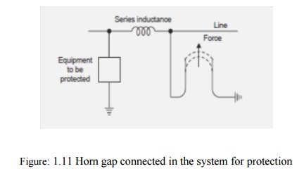
Whenever a surge voltage exceeds the breakdown value of the gap a discharge takes place and the energy content in the rest part of the wave is by-passed to the ground. An arc is set up between the gap, which acts like a flexible conductor and rises upwards under the influence of the electro-magnetic forces, thus increasing the length of the arc which eventually blows out. There are two major drawbacks of the horn gap; (i) The time of operation of the gap is quite large as compared to the modern protective gear. (ii) If used on isolated neutral the horn gap may constitute a vicious kind of arcing ground. For these reasons, the horn gap has almost vanished from important power lines.
Surge Diverters
The following are the basic requirements of a surge diverter:
· It should not pass any current at normal or abnormal (normally 5% more than the normal voltage) power frequency voltage.
· It should breakdown as quickly as possible after the abnormal high frequency voltage arrives.
· It should not only protect the equipment for which it is used but should discharge the surge current without damaging itself.
· It should interrupt the power frequency follow current after the surge is discharged to ground.
There are mainly three types of surge diverters: (i) Rod gap, (ii) Protector tube or expulsion type of lightning arrester, (iii) Valve type of lightning arrester. Rod gap This type of surge diverter is perhaps the simplest, cheapest and most rugged one. Fig. 1.12 shows one such gap for a breaker bushing. This may take the form of arcing ring. Fig. 1.13 shows the breakdown characteristics (volt-time) of a rod gap.
For a given gap and wave shape of the voltage, the time for breakdown varies approximately inversely with the applied voltage.

The time to flashover for positive polarity is lower than for negative polarities. Also it is found that the flashover voltage depends to some extent on the length of the lower (grounded) rod. For low values of this length there is a reasonable difference between positive (lower value) and negative flashover voltages. Usually a length of 1.5 to 2.0 times the gap spacing is good enough to reduce this difference to a reasonable amount. The gap setting normally chosen is such that its breakdown voltage is not less than 30% below the voltage withstand level of the equipment to be protected. Even though rod gap is the cheapest form of protection, it suffers from the major disadvantage that it does not satisfy one of the basic requirements of a lightning arrester listed at no. (iv) i.e., it does not interrupt the power frequency follow current. This means that every operation of the rod gap results in a L-G fault and the breakers must operate to de-energize the circuit to clear the flashover. The rod gap, therefore, is generally used as back up protection.
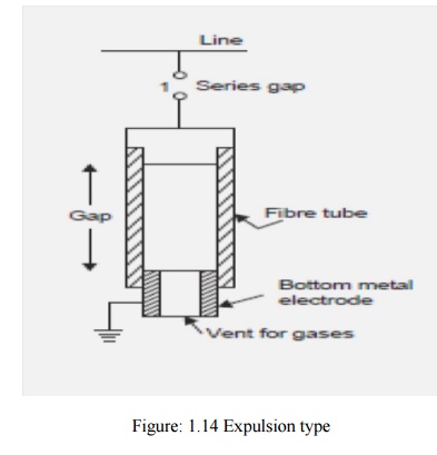
Expulsion type of lightning arrester
An improvement of the rod gap is the expulsion tube which consists of (i) a series gap (1) external to the tube which is good enough to withstand normal system voltage, thereby there is no possibility of corona or leakage current across the tube; (ii) a tube which has a fiber lining on the inner side which is a highly gas evolving material; (iii) a spark gap (2) in the tube; and (iv) an open vent at the lower end for the gases to be expelled (Fig. 1.14). It is desired that the breakdown voltage of a tube must be lower than that of the insulation for which it is used. When
Related Topics