Chapter: High Voltage Engineering : Over Voltages in Electrical Power Systems
Lightning Phenomenon
LIGHTNING PHENOMENON
At the earthling point a heavy impulse current reaching the order of tens of kilo amperes occurs, which is responsible for the known damage of lightning. The velocity of progression of the return stoke is very high and may reach half the speed of light. The corresponding current heats its path to temperatures up to 20,000┬░C, causing the explosive air expansion that is heard as thunder. The current pulse rises to its crest in a few microseconds and decays over a period of tens or hundreds of microseconds.
Facts about Lightning
┬Ę A strike can average 100 million volts of electricity
┬Ę Current of up to 100,000 amperes
┬Ę Can generate 54,000
┬Ę Lightning strikes somewhere on the Earth every second
┬Ę Kills hundreds of people every year.
┬Ę Use The Five Second Rule Light travels at about 186,291 miles/second
┬Ę Sound travels at only 1,088 feet/second
┬Ę You will see the flash of lightning almostimmediately5280/1088= 4.9
┬Ę About 5 seconds for sound to travel 1 mile1 miles (statute) is equal to 1,609.34 meters.1 Feet are equal to 0.30 meters.
1. Lightning Voltage Surges
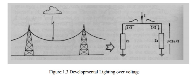
The most severe lightning stroke is that which strikes a phase conductor on the transmission line
It produces the highest overvoltage for a given stroke current.
The lightning stroke injects its current into a termination impedance Z, which in this case is half the line surge impedance Zo since the current will flow in both directions as shown
In Figure1.3. Therefore, the voltage surge magnitude at the striking points = (┬Į) IZo The lightning current magnitude is rarely less than 10 kA.
For typical overhead line surge impedance Zo of 300 ╬®, the lightning surge voltage will Probably have a magnitude in excess of1500 kV.
EFFECT OF LIGHTNING
The impedance of the lightning channel itself is much larger than 1/2Zo (it is believed to range from l00to 3000 ╬®).
┬Ę Lightning voltage surge will have the same shape characteristics.
┬Ę In practice the shapes and magnitudes of lightning surge waves get modified by their
┬Ę Reflections at points of discontinuity as they travel along transmission lines.
┬Ę Lightning strokes represent true danger to life, structures, power systems, and
┬Ę Communication networks.
┬Ę Lightning is always a major source of damage to power systems where equipment
┬Ę Insulation may break down, under the resulting overvoltage and the subsequent high-
┬Ę Energy discharge.
Lightning has been a source of wonder to mankind for thousands of years. Scotland points out that any real scientific search for the first time was made into the phenomenon of lightning by Franklin in18th century. Before going into the various theories explaining the charge formation in a thunder cloud and the mechanism of lightning, it is desirable to review some of the accepted facts concerning the thunder.
2. Cloud And The Associated Phenomenon.
The height of the cloud base above the surrounding ground level may vary from 160 to 9,500m. The charged centers which are responsible for lightning are in the range of 300 to 1500 m.
The maximum charge on a cloud is of the order of 10 coulombs which is built up exponentially
over a period of perhaps many seconds or even minutes. The maximum potential of a cloud lies approximately within the range of 10 MV to 100 MV.
The energy in a lightning stroke may be of the order of 250 kWhr.
Raindrops:
Raindrops elongate and become unstable under an electric field, the limiting diameter being0.3 cm in a field of 100 kV/cm. A free falling raindrop attains a constant velocity with respect to the air depending upon its size. This velocity is 800 cms/sec. for drops of the size 0.25 cm dia. and is zero for spray. This means that in case the air currents are moving upwards with a velocity greater than 800 cm/sec, no rain drop can fall. Falling raindrops greater than 0.5 cm in dia become unstable and break up into smaller drops. When a drop is broken up by air currents, the water particles become positively charged and the air negatively charged. When ice crystal strikes with air currents, the ice crystal is negatively charged and the air positively charged.
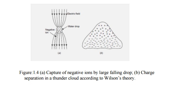
WilsonŌĆÖs Theory of Charge Separation WilsonŌĆśs theory is based on the assumption that a large number of ions are present in the atmosphere. Many of these ions attach themselves to small dust particles and water particles. It also assumes that an electric field exists in the earthŌĆśs atmosphere during fair weather which is directed downwards towards the earth (Figure.1.4 (a)). The intensity of the field is approximately 1 volt/cm at the surface of the earth and decreases gradually with height so that at 9,500 m it is only about 0.02 V/cm. A relatively large raindrop (0.1 cm radius) falling in this field becomes polarized, the upper side acquires a negative.
WilsonŌĆÖs Theory of Charge Separation
WilsonŌĆśs theory is based on the assumption that a large number of ions are present in the atmosphere. Many of these ions attach themselves to small dust particles and water particles. It also assumes that an electric field exists in the earthŌĆśs atmosphere during fair weather which is directed downwards towards the earth (Figure.1.4 (a)). The intensity of the field is approximately 1 volt/cm at the surface of the earth and decreases gradually with height so that at 9,500 m it is only about 0.02 V/cm. A relatively large raindrop (0.1 cm radius) falling in this field becomes polarized, the upper side acquires a negative charge and the lower side a positive charge. Subsequently, the lower part of the drop attracts ŌĆōve charges from the atmosphere which are available in abundance in the atmosphere leaving a preponderance of positive charges in the air.
The upwards motion of air currents tends to carry up the top of the cloud, the +ve air and smaller drops that the wind can blow against gravity. Meanwhile the falling heavier raindrops which are negatively charged settle on the base of the cloud. It is to be noted that the selective action of capturing ŌĆōve charges from the atmosphere by the lower surface of the drop is possible. No such selective action occurs at the upper surface. Thus in the original system, both the positive and negative charges which were mixed up, producing essentially a neutral space charge, are now separated.
Thus according to WilsonŌĆśs theory since larger negatively charged drops settle on the base of the cloud and smaller positively charged drops settle on the upper positions of the cloud, the lower base of the cloud is negatively charged and the upper region is positively charged (Figure.1.4 (b)).SimpsonŌĆÖs and Scarse Theory SimpsonŌĆśs theory is based on the temperature variations in the various regions of the cloud. When water droplets are broken due to air currents, water droplets acquire positive charges whereas the air is negatively charged. Also when ice crystals strike with air, the air is positively charged and the crystals negatively charged. The theory is explained with the help of Fig. 1.5.
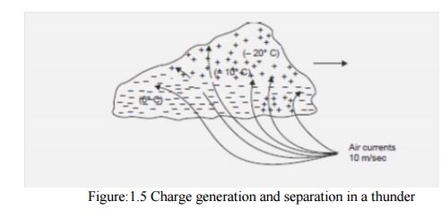
cloud according to SimpsonŌĆśs theory Let the cloud move in the direction from left to right as shown by the arrow. The air currents are also shown in the diagram. If the velocity of the air currents is about 10 m/sec in the base of the cloud, these air currents when collide with the water particles in the base of the cloud, the water drops are broken and carried upwards unless they combine together and fall down in a pocket as shown by a pocket of positive charges (right bottom region in Fig. 7.23). With the collision of water particles we know the air is negatively charged and the water particles positively charged. These negative charges in the air are immediately absorbed by the cloud particles which are carried away upwards with the air currents. The air currents go still higher in the cloud where the moisture freezes into ice crystals.
The air currents when collide with ice crystals the air is positively charged and it goes in the upper region of cloud whereas the negatively charged ice crystals drift gently down in the lower region of the cloud. This is how the charge is separated in a thundercloud. Once the charge separation is complete, the conditions are now set for a lightning stroke.
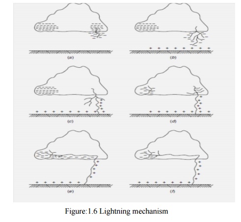
Mechanism of Lightning Stroke Lightning phenomenon is the discharge of the cloud to the ground. The cloud and the ground form two plates of a gigantic capacitor and the dielectric medium is air. Since the lower part of the cloud is negatively charged, the earth is positively charged by induction. Lightning discharge will require the puncture of the air between the cloud and the earth. For breakdown of air at STP condition the electric field required is 30 kV/cm peak. But in a cloud where the moisture content in the air is large and also because of the high altitude (lower pressure) it is seen that for breakdown of air the electric field required is only 10 kV/cm. The mechanism of lightning discharge is best explained with the help of Fig. 1.6. After a gradient of approximately 10 kV/cm is set up in the cloud, the air surrounding gets ionized. At this a streamer (Fig. 1.6(a)) starts from the cloud towards the earth which cannot be detected with the naked eye; only a spot travelling is detected.
The current in the streamer is of the order of 100 amperes and the speed of the streamer is 0.16 m/╬╝ sec. This streamer is known as pilot streamer because this leads to the lightning phenomenon. Depending upon the state of ionization of the air surrounding the streamer, it is branched to several paths and this is known as stepped leader (Fig.1.6(b)). The leader steps are of the order of 50 m in length and are accomplished in about a microsecond. The charge is brought from the cloud through the already ionized path to these pauses. The air surrounding these pauses is again ionized and the leader in this way reaches the earth (Fig.1.6(c)).Once the stepped leader has made contact with the earth it is believed that a power return stroke(Fig. 1.6(c)) moves very fast up towards the cloud through the already ionized path by the leader. This streamer is very intense where the current varies between 1000 amps and 200,000 amps and the speed is about 10% that of light. It is here where the ŌĆōve charge of the cloud is being neutralized by the positive induced charge on the earth (Fig. 1.6 (d)).
It is this instant which gives rise to lightning flash which we observe with our naked eye. There may be another cell of charges in the cloud near the neutralized charged cell. This charged cell will try to neutralize through this ionized path. This streamers known as dart leader (Fig.1.6 (e)). The velocity of the dart leader is about 3% of the velocity of light. The effect of the dart leader is much more severe than that of the return stroke. The discharge current in the return streamer is relatively very large but as it lasts only for a few microseconds the energy contained in the streamer is small and hence this streamer is known as cold lightning stroke whereas the dart leader is known as hot lightning stroke because even though the current in this leader is relatively smaller but it lasts for some milliseconds and therefore the energy contained in this leader is relatively larger.
It is found that each thunder cloud may contain as many as 40 charged cells and a heavy lightning stroke may occur. This is known as multiple stroke. 1.2.3 Line Design Based On Lightning The severity of switching surges for voltage 400 kV and above is much more than that due to lightning voltages. All the same it is desired to protect the transmission lines against direct lightning strokes. The object of good line design is to reduce the number of outages caused by lightning. To achieve this following actions are required. (I) The incidence of stroke on to power conductor should be minimized. (ii) The effect of those strokes which are incident on the system should be minimized. To achieve (i) we know that lightning normally falls on tall objects; thus tall towers are more vulnerable to lightning than the smaller towers. In order to keep smaller tower height for a particular ground clearance, the span lengths will decrease which requires more number of towers and hence the associated accessories like insulators etc. The cost will go up very high. Therefore, a compromise has to be made so that adequate clearance is provided, at the same time keeping longer span and hence lesser number of towers.
With a particular number of towers the chances of incidence of lightning on power conductor scan be minimized by placing a ground wire at the top of the tower structure. . The tower presents a discontinuity to the travelling waves; therefore they suffer reflections and refraction. The system is, then, equivalent to a line bifurcated at the towerpoint.We know that the voltage and current transmitted into the tower will depend upon the surge impedance of the tower and the ground impedance (tower footing resistance) of the tower. If it is low, the wave reflected back up the tower will largely remove the potential existing due to the incident wave. In this way the chance of flashover is eliminated. If, on the other hand, the incident wave encounters high ground impedance, positive reflection will take place and the potential on the top of the tower structure will be raised rather than lowered. It is, therefore, desired that for good line design high surge impedances in the ground wire circuits, the tower structures and the tower footing should be avoided.
Related Topics