Chapter: High Voltage Engineering : Over Voltages in Electrical Power Systems
Mechanism of Lightning Stroke
Mechanism of Lightning Stroke
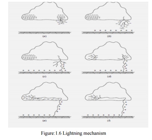
Mechanism of Lightning Stroke Lightning phenomenon is the discharge of the cloud to the ground. The cloud and the ground form two plates of a gigantic capacitor and the dielectric medium is air. Since the lower part of the cloud is negatively charged, the earth is positively charged by induction. Lightning discharge will require the puncture of the air between the cloud and the earth. For breakdown of air at STP condition the electric field required is 30 kV/cm peak. But in a cloud where the moisture content in the air is large and also because of the high altitude (lower pressure) it is seen that for breakdown of air the electric field required is only 10 kV/cm. The mechanism of lightning discharge is best explained with the help of Fig. 1.6. After a gradient of approximately 10 kV/cm is set up in the cloud, the air surrounding gets ionized. At this a streamer (Fig. 1.6(a)) starts from the cloud towards the earth which cannot be detected with the naked eye; only a spot travelling is detected.
The current in the streamer is of the order of 100 amperes and the speed of the streamer is 0.16 m/μ sec. This streamer is known as pilot streamer because this leads to the lightning phenomenon. Depending upon the state of ionization of the air surrounding the streamer, it is branched to several paths and this is known as stepped leader (Fig.1.6(b)). The leader steps are of the order of 50 m in length and are accomplished in about a microsecond. The charge is brought from the cloud through the already ionized path to these pauses. The air surrounding these pauses is again ionized and the leader in this way reaches the earth (Fig.1.6(c)).Once the stepped leader has made contact with the earth it is believed that a power return stroke(Fig. 1.6(c)) moves very fast up towards the cloud through the already ionized path by the leader. This streamer is very intense where the current varies between 1000 amps and 200,000 amps and the speed is about 10% that of light. It is here where the –ve charge of the cloud is being neutralized by the positive induced charge on the earth (Fig. 1.6 (d)).
It is this instant which gives rise to lightning flash which we observe with our naked eye. There may be another cell of charges in the cloud near the neutralized charged cell. This charged cell will try to neutralize through this ionized path. This streamers known as dart leader (Fig.1.6 (e)). The velocity of the dart leader is about 3% of the velocity of light. The effect of the dart leader is much more severe than that of the return stroke. The discharge current in the return streamer is relatively very large but as it lasts only for a few microseconds the energy contained in the streamer is small and hence this streamer is known as cold lightning stroke whereas the dart leader is known as hot lightning stroke because even though the current in this leader is relatively smaller but it lasts for some milliseconds and therefore the energy contained in this leader is relatively larger.
It is found that each thunder cloud may contain as many as 40 charged cells and a heavy lightning stroke may occur. This is known as multiple stroke. 1.2.3 Line Design Based On Lightning The severity of switching surges for voltage 400 kV and above is much more than that due to lightning voltages. All the same it is desired to protect the transmission lines against direct lightning strokes. The object of good line design is to reduce the number of outages caused by lightning. To achieve this following actions are required. (I) The incidence of stroke on to power conductor should be minimized. (ii) The effect of those strokes which are incident on the system should be minimized. To achieve (i) we know that lightning normally falls on tall objects; thus tall towers are more vulnerable to lightning than the smaller towers. In order to keep smaller tower height for a particular ground clearance, the span lengths will decrease which requires more number of towers and hence the associated accessories like insulators etc. The cost will go up very high. Therefore, a compromise has to be made so that adequate clearance is provided, at the same time keeping longer span and hence lesser number of towers.
With a particular number of towers the chances of incidence of lightning on power conductor scan be minimized by placing a ground wire at the top of the tower structure. . The tower presents a discontinuity to the travelling waves; therefore they suffer reflections and refraction. The system is, then, equivalent to a line bifurcated at the towerpoint.We know that the voltage and current transmitted into the tower will depend upon the surge impedance of the tower and the ground impedance (tower footing resistance) of the tower. If it is low, the wave reflected back up the tower will largely remove the potential existing due to the incident wave. In this way the chance of flashover is eliminated. If, on the other hand, the incident wave encounters high ground impedance, positive reflection will take place and the potential on the top of the tower structure will be raised rather than lowered. It is, therefore, desired that for good line design high surge impedances in the ground wire circuits, the tower structures and the tower footing should be avoided.
Related Topics