Chapter: Design of Electrical Machines : Induction Motors
No load current - Design of Induction Motors
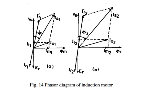
No load
current: As seen from Fig 14, the no load current of an induction motor has two components
magnetizing component, Im and iron loss component, Iw.
Phase relation between these currents is shown in Fig. 14.
Thus the
no load current I0 = √(Im)2 + (Iw)2
amps
Magnetising
current: Magnetising current of an induction motor is responsible for producing
the required amount of flux in the different parts of the machine. Hence this
current can be calculated from all the magnetic circuit of the machine. The
ampere turns for all the magnetic circuit such as stator core, stator teeth,
air gap, rotor core and rotor teeth gives the total ampere turns required for
the magnetic circuit. The details of the magnetic circuit calculations are
studied in magnetic circuit calculations. Based on the total ampere turns of
the magnetic circuit the magnetizing current can be calculated as
Magnetising
current Im= p AT30 / (1.17 kw Tph )
where p –
no of pairs of poles, AT30 – Total ampere turns of the magnetic
circuit at 300 from the centre of the pole, Tph – Number
of stator turns per phase.
Iron loss
component of current: This component of current is responsible for supplying
the iron losses in the magnetic circuit. Hence this component can be calculated
from no load losses and applied voltage.
Iron loss
component of current Iw=
Total no load losses / ( 3 x phase voltage)
No load
Power Factor: No load power factor of an induction motor is very poor. As the
load on the machine increases the power factor improves. No load power factor
can be calculated knowing the components of no load current.
No load
power factor cosΦ0 = Iw
/ I0
Ex. While
designing the stator of a 3 phase 10 kW, 400 volts, 50 Hz, 4 pole, wound rotor induction
motor, following data are obtained.
Internal
diameter of stator = 0.19 m
Gross
length = 0.125 m
Number of
stator slots = 36
Number of
conductors/slot = 38
Dimension
of stator slot = 1.1 cm x 3.5 cm
Depth of
the stator core = 3 cm
Number of
rotor slots = 30
Dimension
of the rotor slot = 0.7 cm x 3.0 cm
Depth of
rotor core = 3.0 cm
Carter’s
coefficient for the air gap = 1.33
Based on
the above data, calculate the following performance data for this motor.
(i) Flux
per pole (ii) Iron losses (iii) Active component of no load current
(iv) No load current
(v) No
load power factor
Soln. (i) Flux per pole
Total
number of stator conductors = 36 x 38 = 1368
Stator
turns per phase Tph = 1368 /6 = 228
Assuming
star delta connection for the motor Vph = 400 volts
Assuming Eph = Vph = 400 volts,
winding factor = 0.955
Air gap
flux per pole Φ = Eph/(4.44fTph kw)
= 400/(
4.44 x 50 x 228 x 0.955)
= 0.00827
wb
(ii) Iron
losses
Total
Iron losses = Iron losses in stator teeth + Iron losses in stator core Iron
losses in stator teeth:
For the
given stator length assuming one ventilating duct of width 1cm and iron space
factor of 0.95,
Li
= (L – nd x wd)ki
= (0.125 -1
x 0.01)0.95
= 0.109 m
Diameter
at 1/3rd height, D' = D + 1/3 x hts x 2 = 0.19
+ 1/3 x 0.035 x 2 = 0.213 m
Slot
pitch at 1/3rd height = τ's = π x D' /Ss =
π x 0.213 /36 = 0.0186 m
Tooth
width at this section = b't = τ's – bs
= 0.0186 – 0.011 = 0.0076 m
Area of
the stator tooth per pole A't
= b't x li x number
of teeth per pole
= b't
x li x Ss
/p = 0.0076 x 0.109 x 36/4
= 0.00746
m2
Mean flux
density in stator teeth B't =
Φ / A't =
0.00827/ 0.00746 = 1.10 9 Tesla
Maximum
flux density in stator tooth =1.5 x 1.109
= 1.66 Tesla
Volume of
all the stator teeth = b't x li x height
of teeth x number of teeth
= 0.0076 x
0.109 x 0.035 x 36
= 0.001044
m3
Weight of
all the teeth = volume x density Assuming a density of 7.8 x 10³ kg/
m3
Weight of
all the teeth = 0.001044 x 7.8 x 103 = 8.14 kg Total iron losses in
the stator teeth = Total weight x loss/kg
Iron loss
in the material at a flux density of 1.66 Tesla from graph PP-22 of DDH loss/kg
= 23 w/kg
Total
iron losses in the stator teeth = 23 x 8.14 = 187.22 watts
Iron losses in stator core : Sectional area of the
stator core = li x dc = 0.109 x 0.03 =
0.00327 m2
Mean
diameter of the stator core below the slots = 0.19 + 2 x 0.035 + 0.03 = 0.29 m
Volume of the stator core = π x D x
Acs = π x 0.29 x 0.00327 = 0.002979 m3
Weight of the stator core = 0.002979 x 7.8 x 103 = 23.23 kg
Flux
density in stator core = Φc / Acs =
0.00827/(2 x 0.00327) = 1.264 Tesla At this flux density iron loss/kg = 17
watts/kg
Iron
losses in the stator core = 17 x 23.23 = 394.91watts
Total
iron losses in the stator = 187.22 + 394.91= 582.13 watts (iii) Active
component of no load current
Assuming
the friction and windage losses as 1% of output Friction and windage loss = 100
w Total no load losses = 582.13 + 100 = 682.13 watts
Active
component of no load current = Iron loss component of current
Iw=
Total no load losses / ( 3 x phase voltage) = 682.13/( 3 x 400) = 0.568 amps
(iv)
Magnetising current: In order to calculate the magnetizing current ampere turns
required for the various parts of the magnetic circuits are to be calculated.
(a)
Ampere turns for the stator core:
Pole
pitch at he mean diameter of the stator core = π x D/ P =
π x 0.29/ 4 = 0.23 m Length of the
flux path in stator core = 1/3 x 0.23 = 0.077 m
Ampere
turns per meter at a flux density of 1.264 Tesla from graph (PP-22 of DDH) 400
AT
Hence
total ampere turns required for the stator core = 400 x 0.077 = 31
(b) Ampere
turns for the stator teeth:
Length of
the flux path in stator teeth = 0.035m
Flux
density in stator teeth at 300 from the pole centre = 1.36 Bt’
= 1.36 x 1.10 9 =1.508 Tesla Ampere turns per meter at a flux density of
1.508 Tesla (from graph PP-22 of DDH) is 1000 AT
Hence
total ampere turns for the stator teeth = 1000 x 0.035 = 35
(c)
Ampere turns for the air gap:
Length of
the air gap = 0.2 + 2√DL = 0.2
+ 2√0.19 x 0.125 = 0.51 mm Average
flux density in the air gap = Φ/ (π x DL/ P) = 0.4696 Tesla
Carter’s
coefficient for the air gap = 1.33
Air gap
flux density at 300 from the centre of the pole Bg = 1.36
x Bav
= 1.36 x
0.4696 = 0.6387 Tesla
Hence
Ampere turns for the air gap = 796000Bgkglg
ATg = 796000 x 0.687 x 1.33 x 0.51 x 10-3
= 371 AT
(d)
Ampere turns for the rotor Teeth :
Diameter
of the rotor = D -2lg =0.19 –
2 x 0.00051= 0.189 m
Diameter
at 1/3rd height form the narrow end of the teeth Dr’ = D – 2 x 2/3hrs
= 0.189 – 4/3 x 0.03 = 0.149 m
Slot
pitch at 1/3rd height = τ'r = π x Dr' /Sr
= π x 0.149 /30 = 0.0156 m
Tooth
width at this section = b'tr = τ'r – br
= 0.0156 – 0.007 = 0.0086 m
Area of
the stator tooth per pole A'tr = b'tr
x li x number
of teeth per pole
= 0.0086
x 0.107 x 30/4 = 0.0069 m2
Flux
density in rotor teeth at 300 from pole centre = 1.36 x
0.00827/0.0069 = 1.63 Tesla
Ampere
turns/m at this flux density, from graph (PP-22 of DDH) = 2800
Length of
flux path in rotor teeth = 0.03 m
Ampere
turns for the rotor teeth 2800 x 0.03 = 84
(e)
Ampere turns for the rotor core
Depth of
the rotor core dcr = 3 cm
Area of
the rotor core Acr = 0.03 x 0.107 = 0.00321 m2
Flux in
the rotor = ½ x 0.00827 = 0.004135 wb
Flux
density in the rotor core = 0.004135/0.00321= 1.29 Tesla
Ampere
turns/m at this flux density, from graph (PP-22 of DDH) = 380
Mean
diameter of the rotor core = Dr – 2 x hrs – dcr
= 0.189 – 2 x 0.03 – 0.03 = 0.099 m
Pole
pitch at this section = π x 0.099
/4 = 0.078 m
Length of
the flux path in rotor core = 1/3 x 0.078 = 0.026 m Total ampere turns for the
rotor core = 380 x 0.026 =10
Total
Ampere turns for the magnetic circuit = 31 + 35 + 371 + 84 +10 = 531 AT
Magnetising current Im = p(AT30) / (1.17 x Kw
x Tph)
= 2 x 531
/( 1.17 x 0.955 x 228)
= 4.2 amps
(v) No
load current
No load
current per phase Io = √( Iw2 + Im2)
= √( 0.562 + 4.22)
= 4.24 amps
(vi)
No load power factor cos 0
= Iw/I0 = 0.56
/4.24 = 0.132
Related Topics