Chapter: Design of Electrical Machines : Induction Motors
Design of Rotor - Induction Motors
Design of Rotor:
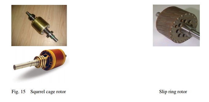
There are two types of rotor construction. One is the squirrel cage rotor and the other is the slip ring rotor. Most of the induction motor are squirrel cage type. These are having the advantage of rugged and simple in construction and comparatively cheaper. However they have the disadvantage of lower starting torque. In this type, the rotor consists of bars of copper or aluminum accommodated in rotor slots. In case slip ring induction motors the rotor complex in construction and costlier with the advantage that they have the better starting torque. This type of rotor consists of star connected distributed three phase windings.
Between stator and rotor is the air gap which is a very critical part. The performance parameters of the motor like magnetizing current, power factor, over load capacity, cooling and noise are affected by length of the air gap. Hence length of the air gap is selected considering the advantages and disadvantages of larger air gap length.
Advantages:
(i) Increased overload capacity
(ii) Increased cooling
(iii) Reduced unbalanced magnetic pull
(iv) Reduced in tooth pulsation
(v) Reduced noise
Disadvantages
(i) Increased Magnetising current
(ii) Reduced power factor
Effect of magnetizing current and its effect on the power factor can be understood from the phasor diagram of the induction motor shown in Fig. 14.
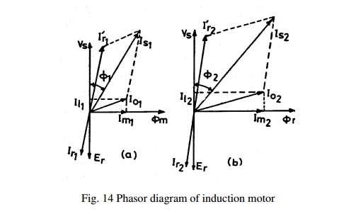
Magnetising current and power factor being very important parameters in deciding the performance of induction motors, the induction motors are designed for optimum value of air gap or minimum air gap possible. Hence in designing the length of the air gap following empirical formula is employed.
Air gap length lg = 0.2 + 2√DL mm
The following Fig. 15 show the different types of rotor construction.
Number of slots: Proper numbers of rotor slots are to be selected in relation to number of stator slots otherwise undesirable effects will be found at the starting of the motor. Cogging and Crawling are the two phenomena which are observed due to wrong combination of number of rotor and stator slots. In addition, induction motor may develop unpredictable hooks and cusps in torque speed characteristics or the motor may run with lot of noise. Let us discuss Cogging and Crawling phenomena in induction motors.
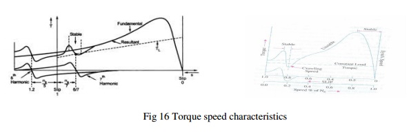
Crawling: The rotating magnetic field produced in the air gap of the will be usually nonsinusoidal and generally contains odd harmonics of the order 3rd, 5th and 7th. The third harmonic flux will produce the three times the magnetic poles compared to that of the fundamental. Similarly the 5th and 7thharmonics will produce the poles five and seven times the fundamental respectively. The presence of harmonics in the flux wave affects the torque speed characteristics. The Fig. 16 below shows the effect of 7th harmonics on the torque speed characteristics of three phase induction motor. The motor with presence of 7th harmonics is to have a tendency to run the motor at one seventh of its normal speed. The 7th harmonics will produce a dip in torque speed characteristics at one seventh of its normal speed as shown in torque speed characteristics.
Cogging: In some cases where in the number of rotor slots are not proper in relation to number of stator slots the machine refuses to run and remains stationary. Under such conditions there will be a locking tendency between the rotor and stator. Such a phenomenon is called cogging.
Hence in order to avoid such bad effects a proper number of rotor slots are to be selected in relation to number of stator slots. In addition rotor slots will be skewed by one slot pitch to minimize the tendency of cogging, torque defects like synchronous hooks and cusps and noisy operation while running. Effect of skewing will slightly increase the rotor resistance and increases the starting torque. However this will increase the leakage reactance and hence reduces the starting current and power factor.
Selection of number of rotor slots: The number of rotor slots may be selected using the following guide lines.
(i) To avoid cogging and crawling: (a)Ss ≠ Sr (b) Ss - Sr ≠ ±3P
(ii) To avoid synchronous hooks and cusps in torque speed characteristics ≠ ±P, ±2P, ±5P.
(iii) To noisy operation Ss - Sr ≠ ±1, ±2, (±P ±1), (±P ±2)
Rotor Bar Current: Bar current in the rotor of a squirrel cage induction motor may be determined by comparing the mmf developed in rotor and stator.
Hence the current per rotor bar is given by Ib = ( Kws x Ss x Z's ) x I'r / ( Kwr x Sr x Z'r ) ;
where Kws – winding factor for the stator, Ss – number of stator slots, Z's – number of
conductors / stator slots, Kwr – winding factor for the rotor, Sr – number of rotor slots, Z'r –
number of conductors / rotor slots and I'r – equivalent rotor current in terms of stator current
and is given by I'r = 0.85 Is where is stator current per phase.
Cross sectional area of Rotor bar: Sectional area of the rotor conductor can be calculated by rotor bar current and assumed value of current density for rotor bars. As cooling conditions are better for the rotor than the stator higher current density can be assumed. Higher current density will lead to reduced sectional area and hence increased resistance, rotor cu losses and reduced efficiency. With increased rotor resistance starting torque will increase. As a guide line the rotor bar current density can be assumed between 4 to 7 Amp/mm2 or may be selected from design data Hand Book.
Hence sectional area of the rotor bars can be calculated as Ab = Ib /δb mm2. Once the cross sectional area is known the size of the conductor may be selected form standard table given in data hand book.
Shape and Size of the Rotor slots: Generally semiclosed slots or closed slots with very small or narrow openings are employed for the rotor slots. In case of fully closed slots the rotor bars are force fit into the slots from the sides of the rotor. The rotors with closed slots are giving better performance to the motor in the following way. (i) As the rotor is closed the rotor surface is smooth at the air gap and hence the motor draws lower magnetizing current. (ii) reduced noise as the air gap characteristics are better (iii) increased leakage reactance and (iv) reduced starting current. (v) Over load capacity is reduced (vi) Undesirable and complex air gap characteristics. From the above it can be concluded that semiclosed slots are more suitable and hence are employed in rotors.
Copper loss in rotor bars: Knowing the length of the rotor bars and resistance of the rotor bars cu losses in the rotor bars can be calculated.
Length of rotor bar lb = L + allowance for skewing
Rotor bar resistance = 0.021 x lb / Ab
Copper loss in rotor bars = Ib2 x rb x number of rotor bars.
End Ring Current: All the rotor bars are short circuited by connecting them to the end rings at both the end rings. The rotating magnetic filed produced will induce an emf in the rotor bars which will be sinusoidal over one pole pitch. As the rotor is a short circuited body, there will be current flow because of this emf induced. The distribution of current and end rings are as shown in Fig. 17 below. Referring to the figure considering the bars under one pole pitch, half of the number of bars and the end ring carry the current in one direction and the other half in the opposite direction. Thus the maximum end ring current may be taken as the sum of the average current in half of the number of bars under one pole.
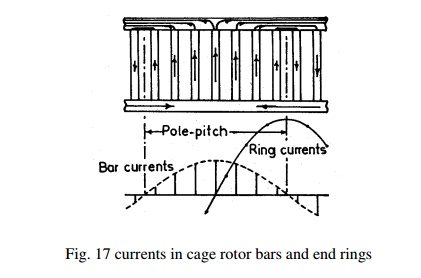
Maximum end ring current Ie(max) = ½ ( Number rotor bars / pole) Ib(av)
= ½ x Sr/P x Ib/1.11
Hence rms value of Ie = 1/2√2 x Sr/P x Ib/1.11
= 1/π x Sr/P x Ib/1.11
Area of end ring: Knowing the end ring current and assuming suitable value for the current density in the end rings cross section for the end ring can be calculated as
Area of each end ring Ae = Ie / δe mm2, current density in the end ring may be assume as 4.5 to 7.5 amp/mm2.
Copper loss in End Rings: Mean diameter of the end ring (Dme) is assumed as 4 to 6 cms less than that of the rotor. Mean length of the current path in end ring can be calculated as lme = πDme. The resistance of the end ring can be calculated as
re = 0.021 x lme / Ae
Total copper loss in end rings = 2 x Ie2 x re
Equivalent Rotor Resistance: Knowing the total copper losses in the rotor circuit and the equivalent rotor current equivalent rotor resistance can be calculated as follows.
Equivalent rotor resistance r'r = Total rotor copper loss / 3 x (Ir' )2
Design of wound Rotor: These are the types of induction motors where in rotor also carries distributed star connected 3 phase winding. At one end of the rotor there are three slip rings mounted on the shaft. Three ends of the winding are connected to the slip rings. External resistances can be connected to these slip rings at starting, which will be inserted in series with the windings which will help in increasing the torque at starting. Such type of induction motors are employed where high starting torque is required.
Number of rotor slots: As mentioned earlier the number of rotor slots should never be equal to number of stator slots. Generally for wound rotor motors a suitable value is assumed for number of rotor slots per pole per phase, and then total number of rotor slots are calculated. So selected number of slots should be such that tooth width must satisfy the flux density limitation. Semiclosed slots are used for rotor slots.
Number of rotor Turns: Number of rotor turns are decided based on the safety consideration of the personal working with the induction motors. The volatge between the slip rings on open circuit must be limited to safety values. In general the voltage between the slip rings for low and medium voltage machines must be limited to 400 volts. For motors with higher voltage ratings and large size motors this voltage must be limited to 1000 volts. Based on the assumed voltage between the slip rings comparing the induced voltage ratio in stator and rotor the number of turns on rotor winding can be calculated.
Voltage ratio Er/ Es = (Kwr x Tr) / (Kws x Ts )
Hence rotor turns per phase Tr = (Er/Es) (Kws/Kwr) Ts
Er = open circuit rotor voltage/phase
Es = stator voltage /phase
Kws = winding factor for stator
Kwr = winding factor for rotor
Ts = Number of stator turns/phase
Rotor Current
Rotor current can be calculated by comparing the amp-cond on stator and rotor
Ir = (Kws x Ss x Z's ) x I'r / ( Kwr x Sr x Z'r ) ;
Kws – winding factor for the stator,
Ss – number of stator slots,
Z's – number of conductors / stator slots,
Kwr – winding factor for the rotor,
Sr – number of rotor slots,
Z'r – number of conductors / rotor slots and
I'r – equivalent rotor current in terms of stator current
I'r = 0.85 Is where Is is stator current per phase.
Area of Rotor Conductor: Area of rotor conductor can be calculated based on the assumed value for the current density in rotor conductor and calculated rotor current. Current density rotor conductor can be assumed between 4 to 6 Amp/mm2
Ar = Ir / δr mm2
Ar < 5mm2 use circular conductor, else rectangular conductor, for rectangular conductor width to thickness ratio = 2.5 to 4. Then the standard conductor size can be selected similar to that of stator conductor.
Size of Rotor slot: Mostly Semi closed rectangular slots employed for the rotors. Based on conductor size, number conductors per slot and arrangement of conductors similar to that of stator, dimension of rotor slots can be estimated. Size of the slot must be such that the ratio of depth to width of slot must be between 3 and 4.
Total copper loss: Length of the mean Turn can be calculated from the empirical formula lmt = 2L + 2.3 τp + 0.08 m
Resistance of rotor winding is given by Rr = (0.021 x lmt x Tr ) / Ar Total copper loss = 3 Ir2 Rr Watts
Flux density in rotor tooth: It is required that the dimension of the slot is alright from the flux density consideration. Flux density has to be calculated at 1/3rd height from the root of the teeth. This flux density has to be limited to 1.8 Tesla. If not the width of the tooth has to be increased and width of the slot has to be reduced such that the above flux density limitation is satisfied. The flux density in rotor can be calculated by as shown below.
Diameter at 1/3rd height Dr' = D - 2/3 x htr x 2
Slot pitch at 1/3rd height = τ'r = π x Dr' /Sr
Tooth width at this section = b'tr = τ'sr – bsr
Area of one rotor tooth = a'tr = b'tr x li
Iron length of the rotor li = (L- wd x nd)ki, ki = iron space factor
Area of all the rotor tooth / pole A'tr = b't x li x Sr /P
Mean flux density in rotor teeth B'tr = Φ / A'tr
Maximum flux density in the rotor teeth < 1.5 times B'tr
Depth of stator core below the slots: Below rotor slots there is certain solid portion which is called depth of the core below slots. This depth is calculated based on the flux
density and flux in the rotor core. Flux density in the rotor core can be assumed to be between 1.2 to 1.4 Tesla. Then depth of the core can be found as follows.
Flux in the rotor core section Φc = ½ Φ
Area of stator core Acr = Φ/2Bcr
Area of stator core Acr = Li x dcr
Hence, depth of the core dcr = Acr / Li
Inner diameter of the rotor can be calculated as follows
Inner diameter of rotor = D - 2lg - 2htr – 2 dcr
Related Topics