Chapter: Electrical machines : Electromechanical Energy Conversion and Concepts in Rotating Machines
Magnetic Fields In Rotating Machines
Magnetic Fields In Rotating Machines
1. Winding factor
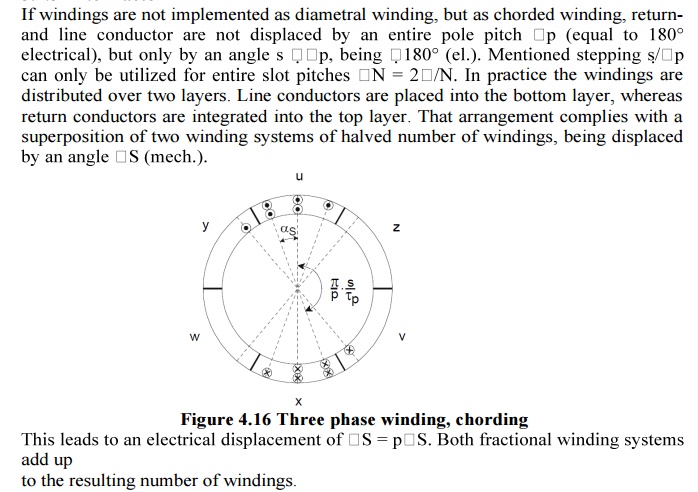
If w windings per phase are not placed in two opposing slots, but are moreover spread overmore than one slot (zone winding) and return conductors are returned under an electric angle smaller than < 180°, the effective number of windings appears smaller than it is in real
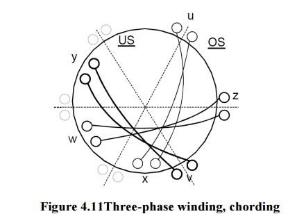
This means is utilized for a supression of harmonics, which cause parasitic torques and losses, influencing proper function of a machine..Actually there is no machine with q =1 Only zoning and chording enable disregarding harmonics.
Rotating Magnetic Field
A symmetric rotating magnetic fieldcan be produced with as few as three coils. The three coils will have to be driven by a symmetric 3-phase AC sine current system, thus each phase will be shifted 120 degrees in phase from the others. For the purpose of this example, the magnetic field is taken to be the linear function of the coil's current.
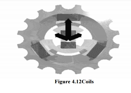
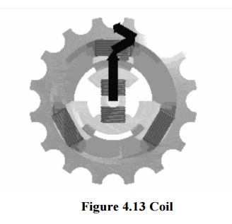
Sine wave current in each of the coils produces sine varying magnetic field on the rotation axis. Magnetic fields add as vectors. Vector sum of the magnetic field vectors of the stator coils produces a single rotating vector of resulting rotating magnetic field.
The result of adding three 120-degrees phased sine waves on the axis of the motor is a single rotating vector. The rotor has a constant magnetic field. The N pole of the rotor will move toward the S pole of the magnetic field of the stator, and vice versa. This magneto-mechanical attraction creates a force which will drive rotor to follow the rotating magnetic field in a synchronous manner.
A permanent magnet in such a field will rotate so as to maintain its alignment with the external field. This effect was utilized in early alternating current electric motors. A rotating magnetic field can be constructed using two orthogonal coils with a 90 degree phase difference in their AC currents. However, in practice such a system would be supplied through a three-wire arrangement with unequal currents.
This inequality would cause serious problems in the standardization of the conductor size. In order to overcome this, three-phase systems are used where the three currents are equal in magnitude and have a 120 degree phase difference. Three similar coils having mutual geometrical angles of 120 degrees will create the rotating magnetic field in this case. The ability of the three phase system to create the rotating field utilized in electric motors is one of the main reasons why three phase systems dominate in the world electric power supply systems.
Rotating magnetic fields are also used in induction motors. Because magnets degrade with time, induction motors use short-circuited rotors (instead of a magnet) which follow the rotating magnetic field of a multicoiled stator. In these motors, the short circuited turns of the rotor develop eddy currents in the rotating field of stator which in turn move the rotor by Lorentz force. These types of motors are not usually synchronous, but instead necessarily involve a degree of 'slip' in order that the current may be produced due to the relative movement of the field and the rotor.
The single coil of a single phase induction motor does not produce a rotating magnetic field, but a pulsating 3-φmotor runs from 1-φ power, but does not start.
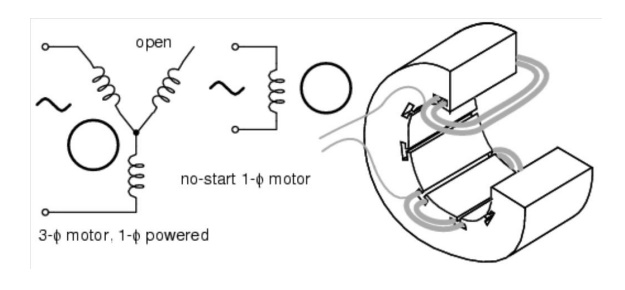
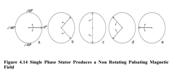
Another view is that the single coil excited by a single phase current produces two counter rotating magnetic field phasor, coinciding twice per revolution at 0o (Figure above-a) and 180o (figure e). When the phasor rotate to 90o and -90o they cancel in figure b. At 45o and -45o (figure c) they are partially additive along the +x axis and cancel along the y axis. An analogous situation exists in figure d. The sum of these two phasor is a phasor stationary in space, but alternating polarity in time. Thus, no starting torque is developed.
However, if the rotor is rotated forward at a bit less than the synchronous speed, It will develop maximum torque at 10% slip with respect to the forward rotating phasor. Less torque will be developed above or below 10% slip. The rotor will see 200% - 10% slip with respect to the counter rotating magnetic field phasor. Little torque (see torque vs. slip curve) other than a double frequency ripple is developed from the counter rotating phasor.
Thus, the single phase coil will develop torque, once the rotor is started. If the rotor is started in the reverse direction, it will develop a similar large torque as it nears the speed of the backward rotating phasor. Single phase induction motors have a copper or aluminum squirrel cage embedded in a cylinder of steel laminations, typical of poly-phase induction motors.
2. Distribution factor(kd)
All w/p windings per pole and phase are distributed over q slots. Any of the
w/pq conductors per slot show a spatial displacement of.
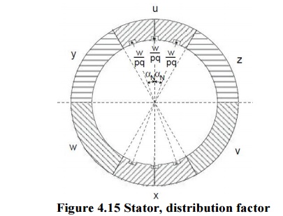
The resulting number of windings wresper phase is computed by geometric addition of all q partial windings w/pq. The vertices of all q phasors per phase, being displaced by ;N (electrically), form a circle. The total angle per phase per phase adds up to q;N.
Purpose: The purpose of utilizing zone winding is to aim
i. slot mmf fundamental waves adding up
ii. harmonics compensating each other, as they suppose to do.
Kd = ER when coils are distributed / ER when coils are concentrated
= 2Rsin(mβ/2) / 2mRsin(β/2)
= sin(mβ/2) / msin(β/2)
Where
m= Slots per pole per phase
β = Slot angle =180 o/ n
n = Slots per pole
The distribution factor is also called winding factor or breadth factor.
3. Pitch factor
Kc = ER when coil is short pitched / ER when coil is full pitched
= 2Ecos(a/2) / 2E
= cos(a/2)
a = Angle of short Pitch
Related Topics