Chapter: Electrical machines : Electromechanical Energy Conversion and Concepts in Rotating Machines
Force in a Multiply Excited Magnetic Field System
Force In A Multiply Excited Magnetic Field System
For continuous energy conversion devices like
Alternators, synchronous motors etc., multiply excited magnetic systems are used. In practice ,doubly excited systems are very much in use.
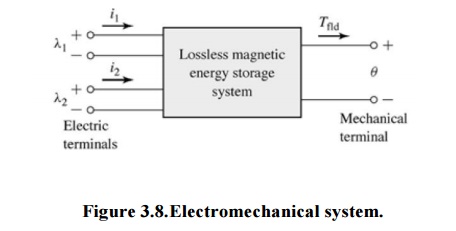
The Figure 3.8 shows doubly excited magnetic system. This system has two independent sources of excitations. One source is connected to coil on stator while other is connected to coil on rotor.
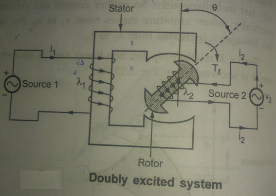
i1= Current due to source 1
i2 = Current due to source 2
l1 = Flux linkages due to i1
l2 = Flux linkages due to i2
q = Angular displacement of rotor
Tf = Torque developed
Due to two sources, there are two sets of three independent variables i.e., (l1, l2, q) or (i1, i2, q).
Case 1 : Independence variables l1, l2, q i.e., l1, l2 are constants.
From the earlier analysis it is known,

While the fields energy is,

Now let
L11 = Self inductance of stator
L22 = Self inductance of rotor
L12 = L21 = Mutual inductance between stator and rotor
l1 = L11 i1 + L12 i2
l2 = L12 i1 + L22 i2
Solve equation (3) and equations (4) to express i1 and i2 interms of l1 and l2 as l1 and l2 are independent varibes.
Multiply equation (3) by L12 and equation (4) by L11,
L12l1 = L11 L12 i1 + L212 i2
L11l2 = L11 L12 i1 + L11 L22 i2
Subtracting the two,
L12l1 - L11l2 = [L212 - L11 L12 ] i1

Note that negative sign is absorbed in defining β.
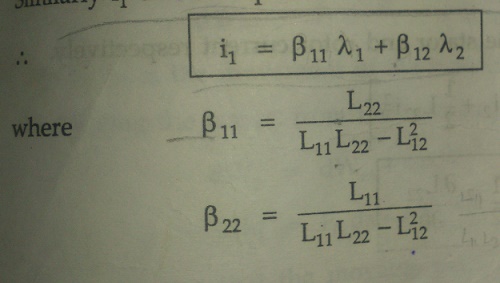
Similarly i1 can be expressed interms of l1 and l2 as,
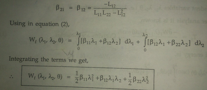
The self and mutual inductances of the coils are dependent on the angular position q of the rotor.
Case 2: Independence variables i1, i2, q i.e. i1 and i2 are constants.
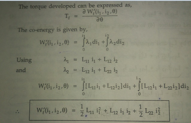
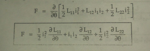
Force in a doubly exited system:

Where i1 and i2 are constants which are the stator and rotor current respectively.
Related Topics