Chapter: Physics : Photonics and fibre Optics
Losses in Optical Fibers
LOSSES IN OPTICAL FIBERS
When light propagates through an optical fiber, a small percentage of light is lost through different mechanisms. The loss of optical power is measured in terms of decibels per km for attenuation losses.
ATTENUATION:
It is defined as the ratio of optical power output (Pout) from a fiber of length ‘L’ to the power output (Pin)
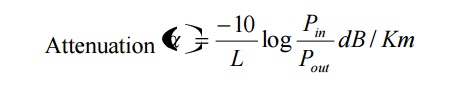
Since attenuation plays a major role in determining the transmission distance, the following attenuation mechanisms are to be considered in designing an optical fiber.
1. Absorption:
Usually absorption of light occurs due to imperfections of the atomic structure such as missing molecules, (OH-), hydroxyl ions, high density cluster of atoms etc., which absorbs light.
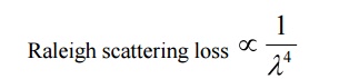
2. Scattering:
Scattering is also a wavelength dependent loss, which occurs inside the fibers. Since the glass is used in fabrication of fibers, the disordered structure of glass will make some variations in the refractive index inside the fiber. As a result, if light is passed through the atoms in the fiber, a portion of light is scattered (elastic scattering) .this type of scattering is called Raleigh scattering.
3. Radiative loss:
Radiative loss occurs in fibers due to bending of finite radius of curvature in optical fibers. The types of bends are
a. Macroscopic bends
b. Microscopic bends
a. Macroscopic bends:
If the radius of the core is large compared to fiber diameter, it may cause large-curvature at the position where the fiber cable turns at the corner. At these corners the light will not satisfy the condition for total internal reflection and hence it escapes out from the fiber. This is called as macroscopic / macro bending losses. Also note that this loss is negligible for small bends.
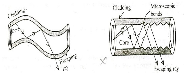
b. Microscopic bends:
Micro-bends losses are caused due to non-uniformities or micro bends inside the fiber as shown. This micro bends in fiber appears due to non uniform pressures created during the cabling of the fiber or even during the manufacturing itself. This lead to loss of light by leakage through the fiber.
Remedy:
Micro-bend losses can be minimized by extruding (squeezing out) a compressible jacket over the fiber. In such cases, even when the external forces are applied, the jacket will be deformed but the fiber will tend to stay relatively straight and safe, without causing more loss.
DISTORTION AND DISPERSION
The optical signal becomes increasingly distorted as it travels along a fiber. This distortion is due to dispersion effect.
Dispersion:
When an optical signal or pulse is sent into the fiber the pulse spreads /broadens as it propagates through the fiber. This phenomenon is called dispersion as shown in the figure.
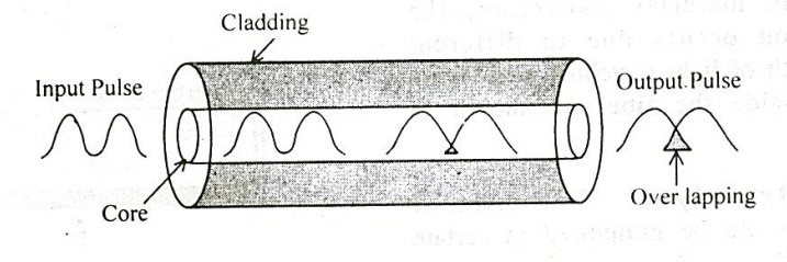
From figure we can see that the pulse received at the output is wider than the input pulse. Hence the output pulse is said to be distorted, due to dispersion effect.
The pulse broadening or dispersion will occur in three ways, viz.,
1. Inter-modal dispersion
2. Material dispersion or chromatic dispersion
3. Waveguide dispersion
Intermodal dispersion:
When more than one mode is propagating through the fiber, then the inter modal dispersion will occur. Since, many modes are propagating; they will have different wavelengths and will take different time to propagate through the fiber, which leads to intermodal dispersion.
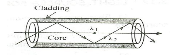
Explanation:
When a ray of light is launched into the fiber, the pulse is dispersed in all possible paths through the core, so called different modes.
Each mode will be different wavelength and has different velocity as shown in the figure. Hence, they reach the end of the fiber at different time. This results in the elongation or stretching of data in the pulse. Thus causes the distorted pulse. This is called intermodal dispersion.
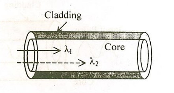
Material dispersion:
In material dispersion, the dispersion occurs due to different wavelength travelling at different speed inside the fibers shown in the figure.
Remedy:
The material dispersion can be minimized at certain wavelengths say 870nm, 1300 nm and 1550 nm; these wavelengths are termed Zero Dispersion wavelengths(ZDW).
Whether light wavelength is lesser than Zero Dispersion wavelengths , it travels slower and when it is higher than ZDW it travels faster. Thus the speed is altered and adjusted in such a way that all the waves passing through the fiber will move with constant speed and hence the material dispersion is minimized.
Note: this dispersion will not occur in single mode fibers
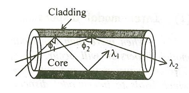
Wave guide dispersion:
The wave guide dispersion arises due to the guiding property of the fiber and due to their different angles at which they incident at the core-cladding interface of the fiber.
In general
Inter-modal dispersion > Material Dispersion> Waveguide dispersion
Related Topics