Chapter: Physics : Photonics and fibre Optics
Fiber Optics and Fiber Construction
FIBER OPTICS
Introduction: FIBER OPTICS
The development of lasers and optical fiber has brought about a revolution in the field of communication systems. Experiments on the propagation of information – carrying light waves through an open atmosphere were conducted. The atmospheric conditions like rain, fog etc affected the efficiency of communication through light waves.
To have efficient communication systems, the information carried by light waves should need a guiding medium through which it can be transmitted safely.
This guiding mechanism is optical fiber. The communication through optical fiber is known as light wave communication or optical communication.
A light beam acting as a carrier wave is capable of carrying more information than that of radio waves and microwaves due to its larger bandwidth.
Currently in most part of the world, fiber optics is used to transmit voice, video and digital data signals using light waves from one place to other place.
Optical fiber:
The optical fiber is a wave guide.
It is made up of transparent dielectrics (SiO2), (glass or plastics).
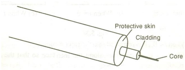
Fiber Construction:
It consists of an inner cylinder made of glass or plastic called core. The core has high refractive index n1.
This core is surrounded by cylindrical shell of glass or plastic called cladding.
The cladding has low refractive index n2. This cladding is covered by a jacket which is made of polyurethane. It protects the layer from moisture and abrasion.
The light is transmitted through this fiber by total internal reflection. The fiber guides light waves to travel over longer distance without much loss of energy.
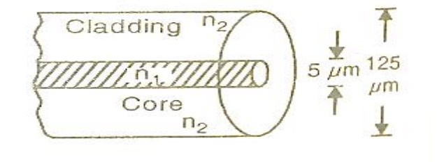
Core diameters range from 5 to 600μm while cladding diameters vary from 125 to 750μm.
Core transmits the light waves. The cladding keeps the light waves within the core by total internal reflection.
Refractive index:
The refractive index or index of refraction of a substance is a measure of the speed of light in that substance. It is expressed as a ratio of the speed of light in vacuum relative to that in the considered medium.
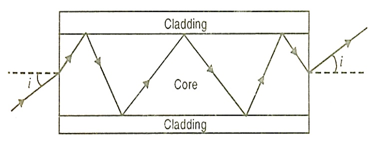
Principle of propagation of light in an optical fiber
The light launched inside the core at one end of the fiber propagates to the other end due to total internal reflection at the core and cladding interface.
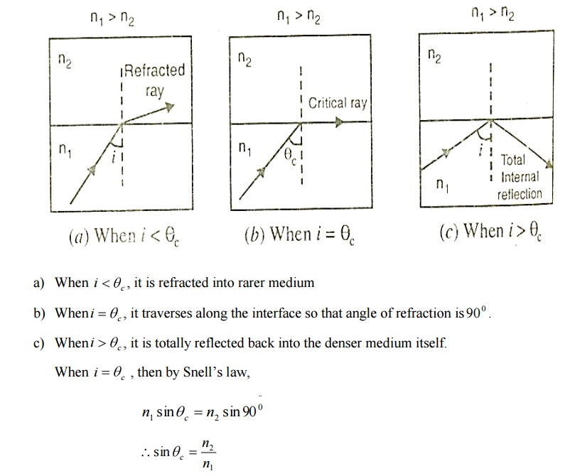
Total internal reflection at the fiber wall can occur only if two conditions are Satisfied.
1. The refractive index of the core material n1 must be higher than that of the cladding n2 surrounding it.
2. At the core – cladding interface, the angle of incidence ( between the ray and normal to the interface) must be greater than the critical angle defined as
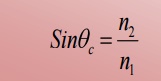
Let the light ray travel from core of refractive index n1 to cladding of refractive index n2 n1 > n2.
Propagation of light through fiber
Consider an optical fiber through which the light is being sent. The end at which light enters is called launching end. Let the refractive indices of the core and cladding be n1 and n2 respectively; n1> n2. Let the refractive index of the medium from which the light is launched be n0.
Let the light ray enter at an angle I to the axis of the fiber
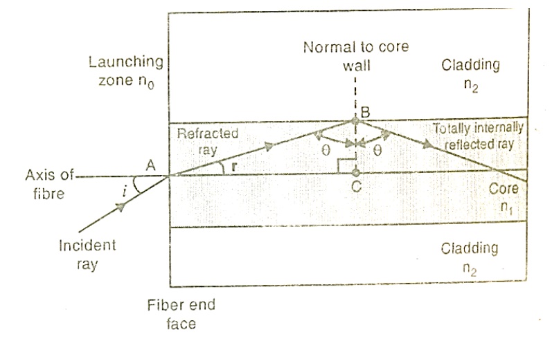
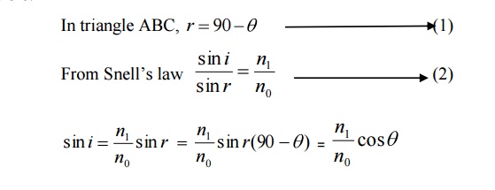
The ray refracts at an angle r.
The ray strikes the core – cladding interface at an angle θ. If θ is greater than the critical angle θc, the ray undergoes total internal reflection at the interface.
Let us now find out up to what maximum value of i at A total internal reflection at B is possible.
If θ is less than the critical angle θc, the ray will be lost by refraction. Therefore, limiting value for containing the beam inside the core by total internal reflection is θc. Let im me the maximum possible angle of incidence at the fiber end face A for which θ = θc.
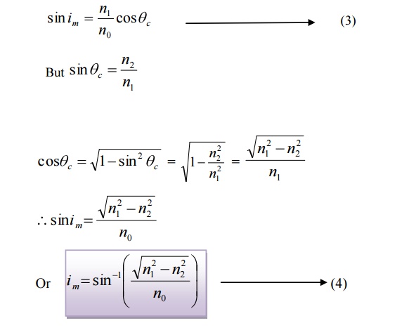
This angle im is called the acceptance angle of the fiber.
Definition: Acceptance angle is defined as the maximum angle that a light ray can have relative to the axis of the fiber and propagate down the fiber.
Or the maximum angle at or below which the light can suffer Total Internal Reflection is called acceptance angle.
Acceptance cone:
An optical fiber accepts only those rays which are incident within a cone having a semi angle im.
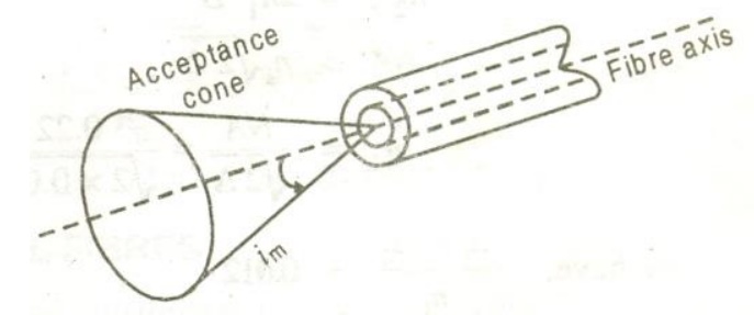
The light rays contained within the cone having a full angle 2im are accepted and transmitted along the fiber. Therefore, the cone is called the acceptance cone.
Light incident at an angle beyond im refracts through the cladding and the corresponding optical energy is lost. It is obvious that the larger the diameter of the core, the larger the acceptance angle.
Numerical Aperture:
Definition:
The numerical aperture (NA) is defined as the sine of the acceptance angle.
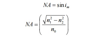
Numerical aperture determines the light gathering ability of the fiber. It is a measure of amount of light that can be accepted by a fiber. NA depends only on the refractive indices of the core and cladding materials. A large NA implies that a fiber will accept large amount of light from the source.
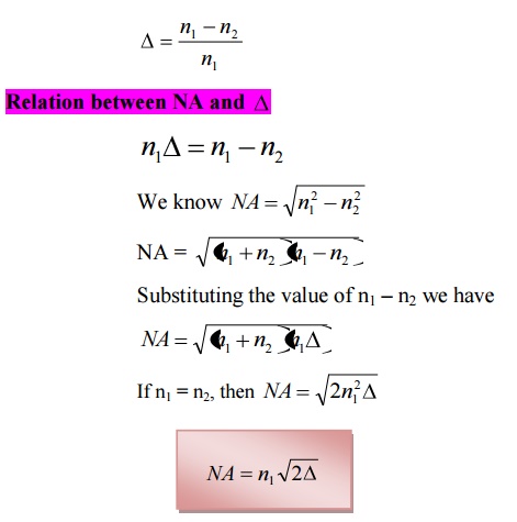
Fractional Index change:
It is the ratio of refractive index difference in core and cladding to the refractive index of the core.
Related Topics