Chapter: Pharmaceutical Drug Analysis: Polarimetry
Instruments for Nephelometry and Turbidimetry

INSTRUMENTS FOR NEPHELOMETRY AND TURBIDIMETRY
Nephelometric and turbidimetric measurements may be made
with a fairly reasonable accuracy and precision by using either standard
instruments available commercially or by improvising other similar de-vices. A
brief description of such available means shall be discussed below :
1. INSTRUMENTS FOR NEPHELOMETRY
In general, nephelometric measurements essentially
require an instrument with a photocell placed in position so that it may
receive selectively the scattered light rather than the transmitted light. As
this principle and geometry also hold good specifically to fluorimeters; and,
therefore, these can be employed as nephelometers by selecting proper filters.
The following instruments are used invariably for
nephelometric measurements, namely :
1.1. Duboscq Colorimeter
In actual practice, the so called ‘visual’ nephelometer
(comparator type) have been more or less super-seded by the photoelectric
instruments Nevertheless, a Duboscq
Colorimeter with a slight modification may be used conveniently for
nephelometric analysis, for instance :
(a) the
path-of-light should be arranged in such a fashion that the light enters the
side of the cups at right angles to the plungers rather than through the
bottoms,
(b)
clear-glass-tube with opaque bottoms are to be used instead of the normal cups,
(c) the
glass-plungers are precisely fitted with opaque sleeves, and
(d) the light
that enters at right angles to the clear-glass-tubes should be monitored carefully
so as to achieve an equal-illumination on either sides.
Now, a standard suspension is placed in one
clear-glass-tube, and the unknown solution is treated exactly in an identical
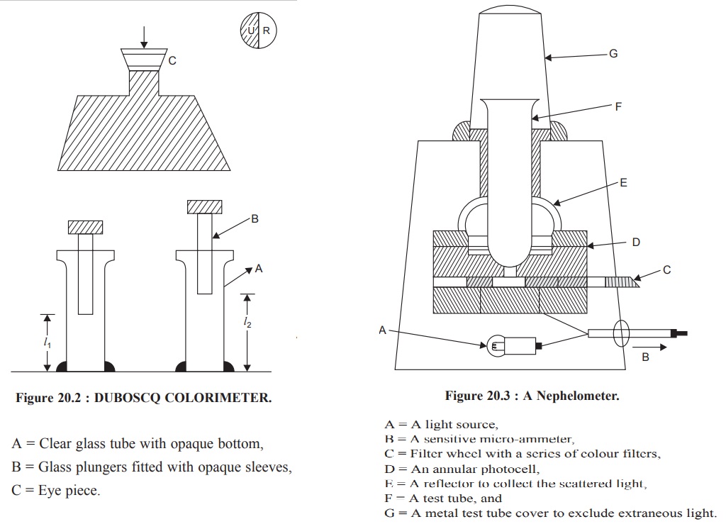
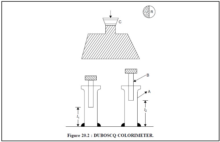
fashion and placed in the other clear-glass-tube. Finally, the dividing line
existing between the two fields in the eye-piece (Figure 20.2) must be
distinctly thin and sharp, and it must disappear when the two fields are
matched properly.
The Duboscq Colorimeter should always be maintained
meticulously neat and clean. The clear-glass-tubes and the plungers are either
rinsed with distilled water or with the solution to be measured.
First of all, it is necessary to ensure that the readings
are zero when the plungers just touch the bottoms of the clear-glass-tubes.
Now, the standard solution is placed in one clear-glass-tube, whereas an equal
volume of the solution in question (unknown) in the other ; bearing in mind the
fact that the clear-glass-tubes should never be filled above their respective
shoulders.

Subsequently, set the unknown solution at a scale reading
of 10.0 mm and simultaneously adjust the standard until the fields are matched
equally. Perform at least five similar adjustments with the clear-glass-tube
(A) containing the standard solution, and calculate the mean value. Care should
always be taken that the plungers (B) always remain below the surface of the
liquid. However, it is advised to visualize the match-point from above and
below :
Assuming Beer’s
Law holds good the concentration of the solution in question (unknown) may
be determined by the help of the following expression :
 ......................(b)
where, l1 = Average readings for the
clear-glass-tube having the solutions of known concentration,
l2 = Average reading for the clear-glass-tube having the
solution of the unknown concentration,
c1 = Concentration of the known solution, and
c2 = Concentration of the unknown solution.
It may, however, be observed that if l2 = 10.0, the standard scale when multiplied by 10
shall give the percentage concentration of the sample in terms of the standard.
1.2. Nephelometer
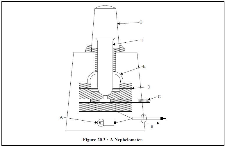
The most important characteristic feature of a nephelometer is the ‘reflector’ that has been specifi-cally
designed so as to collect the light which has undergone scattering by the
particles present in a turbid or cloudy solution. A typical nephelometer is
illustrated in Figure : 20.3, below :

Following are the different parts of a nephelometer :
A = A light source,
B = A sensitive micro-ammeter,
C = Filter wheel with a series of colour filters,
D = An annular photocell,
E = A reflector to collect the scattered light,
F = A test tube, and
G = A metal test tube cover to exclude extraneous light.
The test solution (sample) is placed in a test tube (F)
that has been duly rested on a light source (A) as exhibited in Figure 20.3.
The scattered light caused by the particles in a turbid or cloudy solution is
immedi-ately directed by the reflector (E) on to an annular photocell (D). A
series of standard colour filters are usually provided in the form of a
filter-wheel (C) so as to facilitate analysis of coloured solutions ; taking
care that the filter chosen must be similar to colour to that of the solution.
The current generated after passing through the photocell (i.e., light energy is being converted to electrical energy) is
recorded by a sensitive micro-ammeter (B). The test tube is provided with a
metallic cover (G) to get rid of any extraneous light. Usually a nephelometer
is provided with zero-setting controls, sensitivity adjusting device and a set
of previ-ously matched test tubes.
2. INSTRUMENTS FOR TURBIDIMETRY
In fact, either visual or photoelectric colorimeters may
be satisfactorily employed as turbidimeters. However, the use of the blue
filter normally enhances the sensitivity appreciably. It has been observed that
the light transmitted by a turbid solution does not normally obey the Beer-Lambert Law accurately and
pre-cisely. Therefore, as an usual practice it is advisable to construct a ‘calibration curve’ by employing
several standard solutions. The concentration of the unknown solution may be
read off directly from the above calibra-tion curve as is done in the case of
colorimetric assays.
Related Topics