Chapter: Transmission Lines and Waveguides : Transmission Line Theory
Input and Transfer Impedance
INPUT AND TRANSFER IMPEDANCE:
If the load impedance is not
equal to the source impedance, then all the power that are transmitted from the
source will not reach the load end and hence some power is wasted. This is
represented as impedance mismatch condition. So for proper maximum power
transfer, the impedances in the sending and receiving end are matched. This is
called impedance matching.
Stepped transmission line

A simple example of stepped transmission line
consisting of three segments.
Stepped transmission line is
used for broad range impedance matching. It can be considered as multiple
transmission line segments connected in serial, with the characteristic
impedance of each individual element to be, Z0,i .
And the input impedance can be obtained from
the successive application of the chain relation.

where βi is the
wave number of the ith transmission line segment and li is the
length of this segment, and Zi is the front-end impedance that loads
the ith segment.
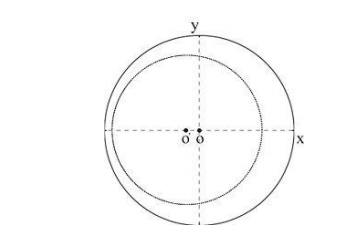
The impedance transformation
circle along a transmission line whose characteristic impedance Z0,i
is smaller than that of the input cable Z0.
Conversely, if Z0,i >
Z0, the impedance curve should be off-centered towards the +x axis.

And as a result, the impedance curve is
off-centered towards the -x axis.
Because the characteristic
impedance of each transmission line segment Z0,i is often different
from that of the input cable Z0, the impedance transformation circle
is off centered along the x axis of the Smith Chart whose impedance
representation is usually normalized against Z0.
Related Topics