Chapter: Mechanical : Kinematics of Machinery : Gears and Trains
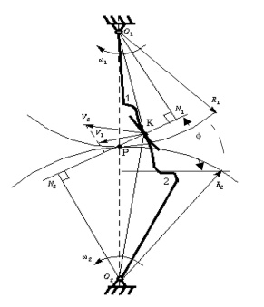
Fundamental Law of Gear-Tooth
Fundamental Law of Gear-Tooth
Pitch point divides the line between the line of centers and its positiond ecides the velocity ratio of the two teeth. The above expression is the fundamental law of gear-tooth action.
Formation of teeth:
Involute teeth
Cycloidal teeth
Involute curve:
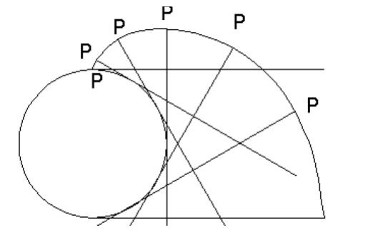
The curve most commonly use d for gear-tooth profiles is the involute of a circle. This involute curve is the path traced by a point on a line as the line Rolls without slipping on the circumference of a circle. It may also be defined asapathtraced by the end of a string, which is originally wrapped on a circle when the string is un wrapped from the circle. The circle from which the involute is derived is called the base circle
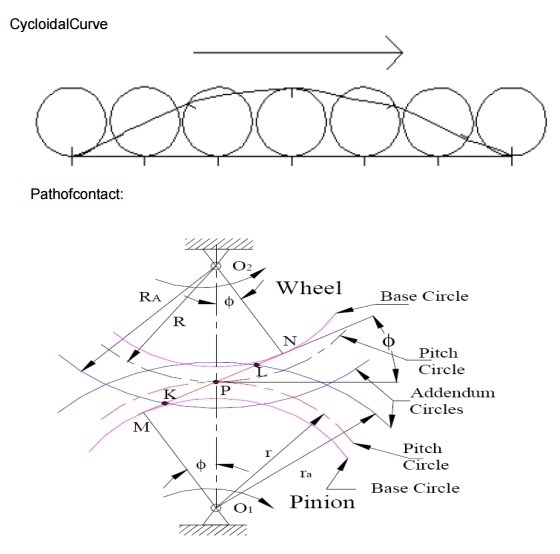
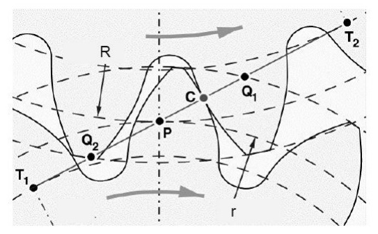
Consider a pinion driving wheel as shown in figure. When the pinion rotates in clockwise, the contact between a pair of involute teeth begin sat K(on the near the base circle of pinion or the outer end of the tooth face on the wheel ) and end sat L (outer end of the tooth face on the pinion or on the flank near the base circle of wheel).
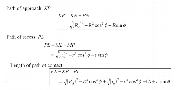
MN is the common normal at the point of contacts and the common tangent to the base circles. The point K is the intersection of the addendum circle of wheel and the common tangent. The point L is the intersection of the addendum circle of pinion and common tangent.
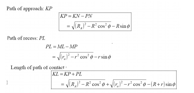
The length of path of contact is the length of common normal cut-off by theaddendum circles of the wheel and the pinion. Thus the length of part of contact is KL which is the sum of the parts of path of contacts KP and PL. Contact length KP is called as path of approach and contact length PL is called as path of recess.
Arc of contact: Arc of contact is the path traced by a point on the pitch circle from the beginning to the end of engagement of a given pair of teeth. In Figure, the arc of contact is EPF or GPH.
The arc GP is known as arc of approach and the arc PH is called arc of recess. The angles subtended by these arcs at O1 are called angle of approach and angle of recess respectively.
Contact Ratio ( or Number of Pairs of Teeth in Contact)
The contact ratio or the number of pairs of teeth in contact is defined as the ratio of the length of the arc of contact to the circular pitch.

Continuous motion transfer requires two pairs of teeth in contact at the ends of the path of contact, though the reisonly one pair in contact in the middle of the path, as in Figure. The average number of teeth in contact is an important parameter-If it is tool owdue the use of inappropriate profile shift sortoan excessive centre distance. Them anufacturinginaccuracies may lead to loss of kinematic continuity-that is to impact, vibration and noise The average number of teeth in contact is also a guide tolod sharing between teeth; it is termed the contact ratio.
The tooth tip of the pinion will then undercut the tooth on the wheel at the root and damages part of the involute profile. This effect is known as interference, and occurs when the teeth are being cut and weakens the tooth at its root.
In general, the phenomenon, when the tip of tooth undercuts the root on its mating gear is known as interference.
Similarly, if the radius of the addendum circles of the wheel increases beyond O2M, then the tip of tooth on wheel will cause interference with the tooth on pinion. The points M and N are called interference points.
Interference may be avoided if the path of the contact does not extend beyond interference points. The limiting value of the radius of the addendum circle of the pinion is O1N and of the wheel is O2M.
The interference may only be prevented, if the point of contact between the two teeth is always on the involute profiles and if the addendum circles of the two mating gears cut the common tangent to the base circles at the points of tangency.
When interference is just prevented, the maximum length of path of contact is MN.
Methods to avoid Interference
1. Height of the teeth may be reduced.
2.Under cut of the radial flank of the pinion.
3.Centre distance may be increased. It leads to increase in pressure angle.
4. By tooth correction, the pressure angle, centre distance and base circles remain unchanged, but tooth thickness of gear will be greater than the pinion tooth thickness.
Minimum number of teeth on the pinion avoid Interference
The pinion turns clockwise and drives the gear as shown in Figure.
Points M and N are called interference points. i.e., if the contact takes place beyond M and N, interference will occur.
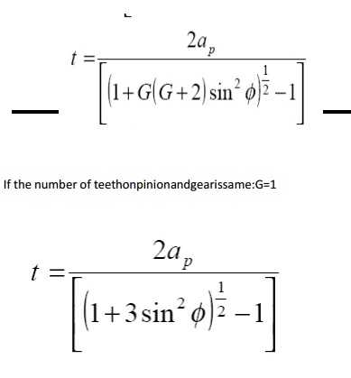
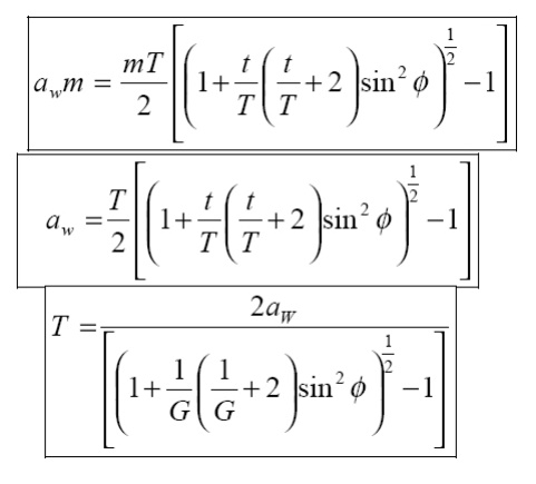
The limiting value of addendum circle radius of pinion is O1N and the limiting value of addendum circle radius of gear is O2M. Considering the critical addendum circle radius of gear, the limiting number of teeth on gear can be calculated.
Let
Ф = pressure angle
R = pitch circle radius of gear = ½ mT
r = pitch circle radius of pinion = ½ mt
T & t = number of teeth on gear & pinion
m = module
Related Topics