Chapter: Communication Theory : Angle Modulation
FM Transmitter
FM TRANSMITTER
ü Indirect method (phase shift) of modulation
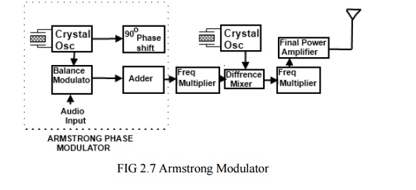
The part
of the Armstrong FM transmitter (Armstrong phase modulator) which is expressed
in dotted lines describes the principle of operation of an Armstrong phase modulator.
It should be noted, first that the output signal from the carrier oscillator is
supplied to circuits that perform the task of modulating the carrier signal.
The oscillator does not change frequency, as is the case of direct FM. These
points out the major advantage of phase modulation (PM), or indirect FM, over
direct FM. That is the phase modulator is crystal controlled for frequency.
The
crystal-controlled carrier oscillator signal is directed to two circuits in
parallel. This signal (usually a sine wave) is established as the reference
past carrier signal and is assigned a value 0°.The balanced modulator is an
amplitude modulator used to form an envelope of double side-bands and to
suppress the carrier signal (DSSC). This requires two input signals, the
carrier signal and the modulating message signal. The output of the modulator
is connected to the adder circuit; here the 90° phase-delayed carriers signal
will be added back to replace the suppressed carrier. The act of delaying the carrier
phase by 90° does not change the carrier frequency or its wave-shape. This
signal identified as the 90° carrier signal.
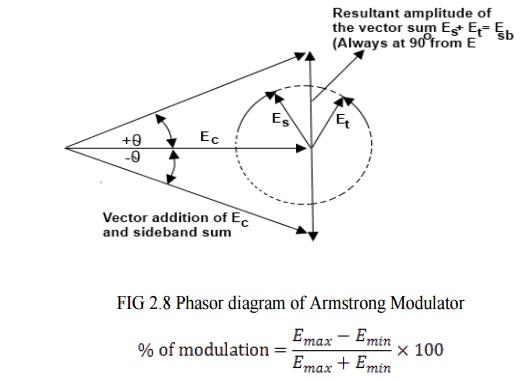
The
carrier frequency change at the adder output is a function of the output phase
shift and is found by. fc = ∆θfs
(in hertz)
When θ is the phase change in radians
and fs is the lowest audio modulating frequency. In most FM radio
bands, the lowest audio frequency is 50Hz. Therefore, the carrier frequency
change at the adder output is 0.6125 x 50Hz = ± 30Hz since 10% AM represents
the upper limit of carrier voltage change, then ± 30Hz is the maximum deviation
from the modulator for PM.
The 90°
phase shift network does not change the signal frequency because the components
and resulting phase change are constant with time. However, the phase of the
adder output voltage is in a continual state of change brought about by the
cyclical variations of the message signal, and during the time of a phase
change, there will also be a frequency change.
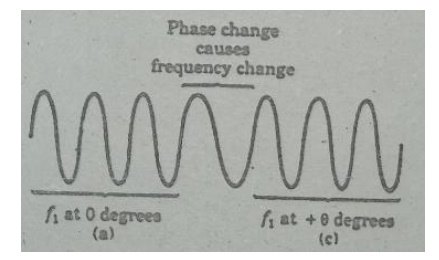
In
figure. (c). during time (a), the signal has a frequency f1, and is
at the zero reference phase. During time (c), the signal has a frequency f1
but has changed phase to θ. During
time (b) when the phase is in the process of changing, from 0 to θ. the frequency is less than f1.
ü Using Reactance modulator direct method
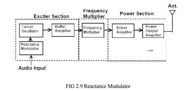
The FM
transmitter has three basic sections.
1. The
exciter section contains the carrier oscillator, reactance modulator and the
buffer amplifier.
2. The
frequency multiplier section, which features several frequency multipliers.
3. The poweroutput
ection, which includes a low- level power amplifier, the final power amplifier,
and the impedance matching network to properly load the power section with the
antenna impedance.
The
essential function of each circuit in the FM transmitter may be described as
follows.
ü The Exciter
1. The
function of the carrier oscillator is to generate a stable sine wave signal at
the rest frequency, when no modulation is applied. It must be able to linearly
change frequency when fully modulated, with no measurable change in amplitude.
2. The
buffer amplifier acts as a constant high-impedance load on the oscillator to
help stabilize the oscillator frequency. The buffer amplifier may have a small
gain.
3. The
modulator acts to change the carrier oscillator frequency by application of the
message signal. The positive peak of the message signal generally lowers the
oscillator's frequency to a point below the rest frequency, and the negative
message peak raises the oscillator frequency to a value above the rest frequency.
The greater the peak-to-peak message signal, the larger the oscillator
deviation.
ü Frequency
multipliers are tuned-input, tuned-output RF amplifiers in which the output
resonant circuit is tuned to a multiple of the input frequency. Common frequency
multipliers are 2x, 3x and 4x multiplication. A 5x Frequency multiplier is
sometimes seen, but its extreme low efficiency forbids widespread usage. Note
that multiplication is by whole numbers only. There can not a 1.5x multiplier,
for instance.
ü The final
power section develops the carrier power, to be transmitted and often has a
low-power amplifier driven the final power amplifier. The impedance matching
network is the same as for the AM transmitter and matches the antenna impedance
to the correct load on the final over amplifier.
ü Frequency Multiplier
A special
form of class C amplifier is the frequency. multiplier. Any class C amplifier
is capable of performing frequency multiplidàtion if the tuned circuit in the
collector resonates at some integer multiple of the input frequency.
For
example a frequency doubler can be constructed by simply connecting a parallel
tuned circuit in the collector of a class C amplifier that resonates at twice
the input frequency. When the collector current pulse occurs, it excites or
rings the tuned circuit at twice the input frequency. A current pulse flows for
every other cycle of the input.
A Tripler
circuit is constructed in the same way except that the tuned circuit resonates
at 3 times the input - frequency. In this way, the tuned circuit receives one
input pulse for every three cycles of oscillation it produces Multipliers can
be constructed to increase the input frequency by any integer factor up to
approximately 10. As' the multiplication factor gets higher, the power output
of the multiplier decreases. For most practical applications, the best result
is obtained with multipliers of 2 and 3.
Another
way to look the operation of class C multipliers is .to .remember that the
non-sinusoidal current pulse is rich in harmonics. Each time the pulse occurs,
the second, third, fourth, fifth, and higher harmonics are generated. The
purpose of the tuned circuit in the collector is to act as a filter to select
the desired harmonics.
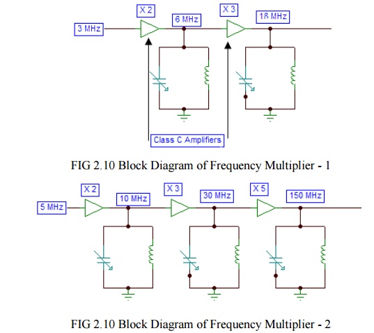
In many
applications a multiplication factor greater than that achievable with a single
multiplier stage is required. In such cases two or more multipliers are
cascaded to produce an overall multiplication of 6. In the second example,
three multipliers provide an overall multiplication of 30. The total
multiplication factor is simply the product of individual stage multiplication
factors.
ü Reactance Modulator
The
reactance modulator takes its name from the fact that the impedance of the
circuit acts as a reactance (capacitive or inductive) that is connected in
parallel with the resonant circuit of the Oscillator. The varicap can only
appear as a capacitance that becomes part of the frequency determining branch
of the oscillator circuit. However, other discrete devices can appear as a
capacitor or as an inductor to the oscillator, depending on how the circuit is
arranged. A colpitts oscillator uses a capacitive voltage divider as the
phase-reversing feedback path and would most likely tapped coil as the
phase-reversing element in the feedback loop and most commonly uses a modulator
that appears inductive.
Related Topics