Chapter: Fundamentals of Database Systems : Conceptual Modeling and Database Design : Data Modeling Using the Entity-Relationship (ER) Model
Example of Other Notation: UML Class Diagrams
Example of Other Notation: UML Class Diagrams
The UML methodology is being used extensively in software design and has
many types of diagrams for various software design purposes. We only briefly
present the basics of UML class diagrams
here, and compare them with ER diagrams. In some ways, class diagrams can be
considered as an alternative notation to ER diagrams. Additional UML notation
and concepts are presented in Section 8.6, and in Chapter 10. Figure 7.16 shows
how the COMPANY ER database schema in Figure 7.15 can be displayed using UML class
diagram notation. The entity types in
Figure 7.15 are modeled as classes in
Figure 7.16. An entity in ER
corresponds to an object in UML.
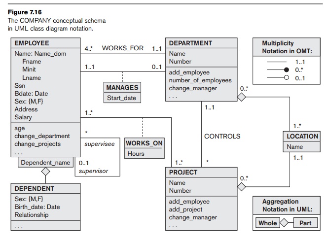
In UML class diagrams, a class
(similar to an entity type in ER) is displayed as a box (see Figure 7.16) that
includes three sections: The top section gives the class name (similar to entity type name); the middle section
includes the attributes; and the
last section includes operations
that can be applied to individual objects (similar to individual entities in an
entity set) of the class. Operations are not
specified in ER diagrams. Consider the EMPLOYEE class in
Figure 7.16. Its attributes are Name, Ssn, Bdate,
Sex, Address, and Salary. The designer can optionally specify the domain
of an attribute if desired, by
placing a colon (:) followed by the domain name or description, as illustrated
by the Name, Sex, and Bdate attributes of EMPLOYEE in Figure 7.16. A composite
attribute is modeled as a structured
domain, as illustrated by the Name
attribute of EMPLOYEE. A multivalued attribute will generally be mod-eled as a separate
class, as illustrated by the LOCATION class in Figure 7.16.
Relationship types are called associations
in UML terminology, and relationship instances are called links. A binary association
(binary relationship type) is repre-sented as a line connecting the
participating classes (entity types), and may option-ally have a name. A relationship
attribute, called a link attribute,
is placed in a box that is connected to the association’s line by a dashed
line. The (min, max) notation described in Section 7.7.4 is used to specify
relationship constraints, which are called multiplicities
in UML terminology. Multiplicities are specified in the form min..max, and an asterisk (*) indicates no maximum limit on
participation. However, the
multiplicities are placed on the opposite
ends of the relationship when compared with the notation discussed in
Section 7.7.4 (compare Figures 7.15 and 7.16). In UML, a single asterisk
indicates a multiplicity of 0..*, and a single 1 indi-cates a multiplicity of 1..1. A recursive
relationship (see Section 7.4.2) is called a reflexive association in UML, and the role names—like the
multiplicities—are placed at the
opposite ends of an association when compared with the placing of role names in
Figure 7.15.
In UML, there are two types of relationships: association and
aggregation. Aggregation is meant to
represent a relationship between a whole object and its component parts, and it has a distinct diagrammatic notation. In
Figure 7.16, we modeled the locations of a department and the single location
of a project as aggre-gations. However, aggregation and association do not have
different structural properties, and the choice as to which type of
relationship to use is somewhat sub-jective. In the ER model, both are
represented as relationships.
UML also distinguishes between unidirectional
and bidirectional associations (or
aggregations). In the unidirectional case, the line connecting the classes is
displayed with an arrow to indicate that only one direction for accessing
related objects is needed. If no arrow is displayed, the bidirectional case is
assumed, which is the default. For example, if we always expect to access the
manager of a department starting from a DEPARTMENT object,
we would draw the association line represent-ing the MANAGES association with an arrow from DEPARTMENT to EMPLOYEE. In addition, relationship instances may be specified to be ordered. For example, we could specify
that the employee objects related to each department through the WORKS_FOR association (relationship) should be ordered by their Salary attribute value. Association (relationship) names are optional in UML, and relationship
attributes are displayed in a box attached with a dashed line to the line
representing the association/aggregation (see Start_date and Hours in Figure 7.16).
The operations given in each class are derived from the functional
requirements of the application, as we discussed in Section 7.1. It is
generally sufficient to specify the operation names initially for the logical
operations that are expected to be applied to individual objects of a class, as
shown in Figure 7.16. As the design is refined, more details are added, such as
the exact argument types (parameters) for each operation, plus a functional
description of each operation. UML has function
descriptions and sequence diagrams to specify some of the operation details, but these are beyond the scope of our
discussion. Chapter 10 will introduce some of these diagrams.
Weak entities can be modeled using the construct called qualified association (or qualified aggregation) in UML; this can
represent both the identifying relationship
and the partial key, which is placed in a box attached to the owner class.
This is illus-trated by the DEPENDENT class and its qualified
aggregation to EMPLOYEE in Figure 7.16. The partial key Dependent_name is
called the discriminator in UML
ter-minology, since its value distinguishes the objects associated with
(related to) the same EMPLOYEE. Qualified associations are not
restricted to modeling weak enti-ties, and they can be used to model other
situations in UML.
This section is not meant to be a complete description of UML class
diagrams, but rather to illustrate one popular type of alternative diagrammatic
notation that can be used for representing ER modeling concepts.
Related Topics