Chapter: Cryptography and Network Security Principles and Practice : Network and Internet Security : IP Security
Encapsulating Security Payload
ENCAPSULATING SECURITY PAYLOAD
ESP can be used to provide confidentiality, data origin authentication, connection- less integrity, an anti-replay service
(a form of partial sequence
integrity), and (lim- ited) traffic flow confidentiality.
The set of services provided depends on options selected at the time of Security
Association (SA) establishment and on the location
of the implementation in a network topology.
ESP can work with a
variety of encryption and authentication algorithms, including authenticated
encryption algorithms such as GCM.
ESP Format
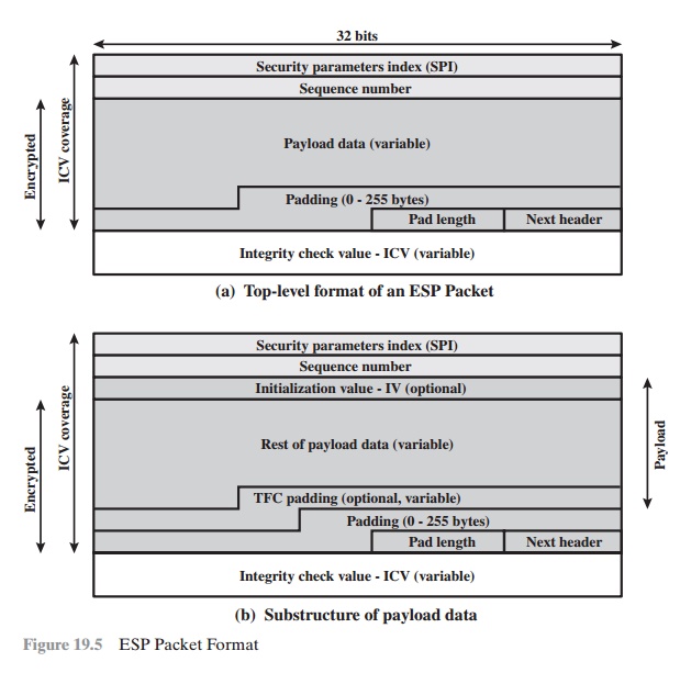
Figure 19.5a shows the top-level
format of an ESP packet.
It contains the following
fields.
•
Security Parameters Index (32 bits): Identifies a security
association.
•
Sequence Number (32 bits): A monotonically increasing counter value;
this provides an anti-replay function, as discussed
for AH.
•
Payload Data (variable): This is a transport-level segment
(transport mode) or IP packet
(tunnel mode) that is protected by encryption.
•
Padding (0 – 255 bytes): The purpose of this field is discussed later.
•
Pad Length (8 bits): Indicates the number of pad bytes
immediately preceding this field.
•
Next Header (8 bits): Identifies the type of data contained in the payload
data field by identifying the first header in that payload (for example, an extension
header in IPv6, or an upper-layer protocol
such as TCP).
•
Integrity Check Value (variable): A variable-length field
(must be an integral
number of 32-bit words) that contains the Integrity Check Value computed over the ESP packet minus the Authentication Data field.
When any combined mode algorithm is employed, the
algorithm itself is expected
to return both decrypted plaintext and a pass/fail
indication for the integrity
check. For combined mode algorithms, the ICV that would normally appear
at the end of the ESP packet (when integrity is selected) may be omitted. When the ICV is omitted and integrity is selected, it is the responsibility of the com- bined mode algorithm to encode within the Payload
Data an ICV-equivalent means
of verifying the integrity of the packet.
Two additional fields may be present in the payload
(Figure 19.5b). An initialization value
(IV), or nonce, is present if this is required by the encryption or authenticated encryption algorithm
used for ESP. If tunnel mode is being used, then the
IPsec implementation may
add traffic flow confidentiality
(TFC) padding after
the Payload Data and before
the Padding field,
as explained subsequently.
Encryption and Authentication Algorithms
The Payload Data, Padding, Pad Length, and
Next Header fields are encrypted by the ESP service. If the algorithm used to
encrypt the payload requires crypto- graphic synchronization data, such as an
initialization vector (IV), then these data may be carried explicitly at the beginning
of the Payload Data field. If included, an IV is usually not encrypted,
although it is often referred to as being part of the ciphertext.
The ICV field is optional. It is present only if the integrity
service is selected and is provided
by either a separate integrity algorithm or a combined mode algo- rithm that uses an ICV. The ICV is computed after
the encryption is performed. This order of processing facilitates
rapid detection and rejection of replayed or bogus packets by the receiver
prior to decrypting the packet, hence potentially reducing the impact of denial of service
(DoS) attacks. It also allows for the possibility of par-
allel processing of packets at the receiver, i.e., decryption can take place
in parallel with integrity checking. Note that because the ICV is not protected by encryption, a keyed
integrity algorithm must be employed
to compute the ICV.
Padding
The Padding field serves several purposes:
•
If an encryption algorithm requires the plaintext to be a multiple of some number
of bytes (e.g., the multiple of a single block for a block cipher), the Padding field is used to expand the plaintext
(consisting of the Payload Data, Padding, Pad Length, and Next Header
fields) to the required length.
•
The ESP format requires
that the Pad Length and Next Header fields be right
aligned within a 32-bit word. Equivalently, the ciphertext must be an integer
multiple of 32 bits.
The Padding field is used to assure this alignment.
Additional padding
may be added to provide
partial traffic-flow confidential- ity by concealing the actual length of the payload.
Anti-Replay Service
A replay attack
is one in which an attacker
obtains a copy of an authenticated packet and later transmits it
to the intended destination. The receipt
of duplicate, authenticated IP packets
may disrupt service
in some way or may have some other
undesired consequence. The Sequence Number field is designed to thwart such attacks.
First, we discuss sequence number generation by the sender, and then we look at how it is processed by the recipient.
When a new SA is established, the sender initializes
a sequence number counter to 0. Each time that a
packet is sent on this SA, the sender increments the counter and places the value in the Sequence
Number field. Thus, the first value to
be used is 1. If anti-replay is enabled (the default), the sender must not
allow the
sequence number to cycle past 232 – 1 back to zero.
Otherwise, there would be multiple valid packets with the same sequence number.
If the limit of 232 – 1 is
reached,
the sender should
terminate this SA and negotiate a new SA with a new key.
Because IP is a connectionless, unreliable service, the protocol does not guar- antee that packets will be delivered
in order and does not guarantee that all packets will be delivered. Therefore,
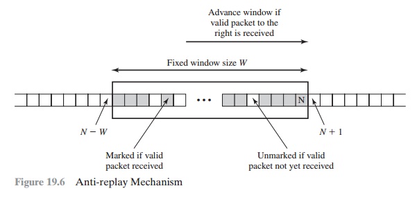
the IPsec authentication document dictates that the receiver should implement a window of size W, with a default
of W = 64. The right edge of the window represents the highest sequence
number, N, so far received for a valid packet. For any packet with a sequence number
in the range from N - W + 1 to N that has been correctly received
(i.e., properly authenticated), the corresponding slot in the window is marked
(Figure 19.6). Inbound processing
proceeds as follows when a packet is received:
1.
If the received packet falls within the window and is new, the MAC is checked.
If the packet is authenticated, the corresponding slot in the window is marked.
2.
If the received
packet is to the right of the window and is new,
the MAC is checked. If the
packet is authenticated, the window is advanced so that this sequence
number is the right edge of the window, and the corresponding slot in the window is marked.
3.
If the received packet is to the left of the window or if authentication fails, the packet is discarded; this is an auditable event.
Transport and Tunnel Modes
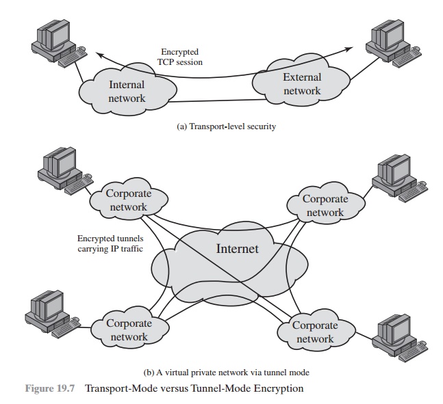
Figure 19.7 shows two
ways in which
the IPsec ESP
service can be used. In the upper part of the figure, encryption
(and optionally authentication) is provided directly between two
hosts. Figure 19.7b
shows how tunnel
mode operation can
be used to set up a virtual private network.
In this example, an organization has four private networks interconnected across the Internet.
Hosts on the internal networks
use the Internet for transport of data but do not interact with other Internet-based hosts. By terminating the tunnels at the security gateway to each
internal network, the
configu- ration allows the hosts to avoid implementing the security
capability. The former technique is supported by a transport mode SA, while the
latter technique uses a tunnel mode SA.
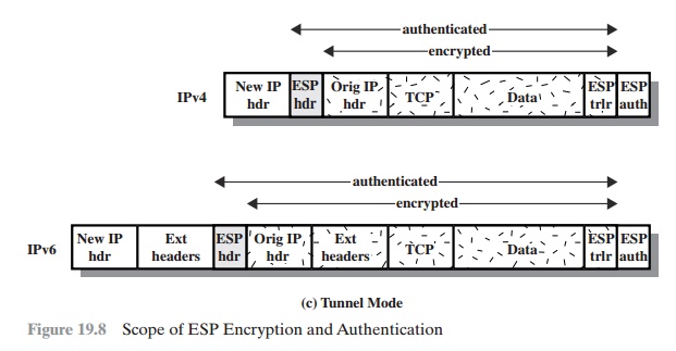
In this section, we look at the scope of ESP
for the two modes. The consid- erations are somewhat different for IPv4 and
IPv6. We use the packet formats of Figure 19.8a as a starting point.
TRANSPORT MODE ESP Transport mode ESP is used
to encrypt and optionally
authenticate the data carried by IP (e.g., a TCP segment),
as shown in Figure 19.8b.
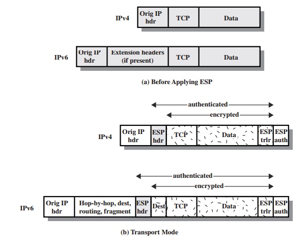
For this mode using IPv4,
the ESP header
is inserted into the IP packet immediately prior to the transport-layer header (e.g., TCP, UDP, ICMP), and an ESP trailer
(Padding, Pad Length, and Next Header fields) is placed
after the IP packet. If authentication is selected, the ESP Authentication Data field is added after the ESP trailer.
The entire transport-level segment
plus the ESP trailer are
encrypted. Authentication covers
all of the ciphertext plus the ESP header.
In the context
of IPv6, ESP is viewed as an end-to-end payload;
that is, it is not
examined or processed by intermediate routers. Therefore, the ESP header
appears after the IPv6 base header and the hop-by-hop, routing, and
fragment extension headers. The destination
options extension header could appear before or after the ESP header, depending on the semantics desired. For IPv6, encryption covers the entire transport-level segment plus the ESP trailer
plus the destination options extension header if it occurs after the ESP header.
Again, authentication covers the
ciphertext plus the ESP header.
Transport mode operation may be summarized
as follows.
1.
At the source, the
block of data consisting of the ESP trailer plus the entire transport-layer segment
is encrypted and the plaintext of this block
is replaced with its
ciphertext to form the IP packet for transmission. Authentication is added if this option
is selected.
2.
The packet
is then
routed to the destination. Each
intermediate router needs to examine and process the IP header plus any
plaintext IP extension headers but does not need to examine
the ciphertext.
3.
The destination node examines
and processes the IP header
plus any plaintext IP extension headers. Then, on
the basis of the SPI in the ESP header, the destination node decrypts the remainder of the packet to recover
the plaintext transport-layer segment.
Transport mode operation provides
confidentiality for any application that uses
it, thus avoiding the need to implement
confidentiality in every individual application. One drawback to this mode is that it is possible to do traffic
analysis on the transmitted packets.
TUNNEL MODE ESP Tunnel
mode ESP is used to encrypt an entire IP packet (Figure 19.8c). For this mode,
the ESP header is prefixed to the packet and then the packet plus the ESP
trailer is encrypted. This method can be used to counter traffic analysis.
Because the IP header contains the
destination address and possibly source routing directives and hop-by-hop
option information, it is not possible simply to transmit the encrypted IP
packet prefixed by the ESP header. Intermediate routers would be unable to process such a packet.
Therefore, it is necessary to encapsulate
the entire block (ESP header plus ciphertext plus Authentication Data, if
present) with a new IP header
that will contain
sufficient information for routing but not for traffic analysis.
Whereas the transport mode is suitable for
protecting connections between hosts that support
the ESP feature,
the tunnel mode is useful
in a configuration that
includes a firewall or other
sort of security
gateway that protects
a trusted network from external networks. In this latter
case, encryption occurs
only between an exter-
nal host and the security gateway or between two security gateways. This
relieves hosts on the internal network
of the processing burden of encryption and simplifies
the key distribution task by reducing the number of needed keys. Further,
it thwarts traffic analysis
based on ultimate
destination.
Consider a case in which an external
host wishes to communicate with a host on
an internal network
protected by a firewall, and in which ESP is implemented in the external host and the firewalls. The following
steps occur for transfer of a trans- port-layer segment from the external host to the internal host.
1.
The source prepares an inner IP
packet with a destination address of the target
internal host. This packet is prefixed by an ESP header; then the packet and ESP trailer are encrypted and
Authentication Data may be added. The resulting block is encapsulated with a new IP header (base
header plus optional extensions such as routing
and hop-by-hop options
for IPv6) whose destination address is
the firewall;
this forms the outer IP packet.
2.
The outer packet is
routed to the destination firewall. Each intermediate router needs to examine and
process the outer IP header plus any
outer IP extension headers but does not need to examine
the ciphertext.
3.
The destination firewall
examines and processes the outer IP header plus any outer IP extension headers.
Then, on the basis of the SPI in the ESP header, the destination node decrypts the remainder
of the packet to recover
the plaintext inner
IP packet. This packet
is then transmitted in the internal network.
4.
The inner packet is
routed through zero or more routers in the internal network to the destination host.
Figure 19.9 shows the protocol architecture
for the two modes.
Related Topics