Chapter: Civil : Prestressed Concrete Structures : Circular Prestressing
Different types of joints used between the slab of prestressed concrete tank
The
different types of joints used between the slab of prestressed concrete tank
Joints
shall be categorized as below:
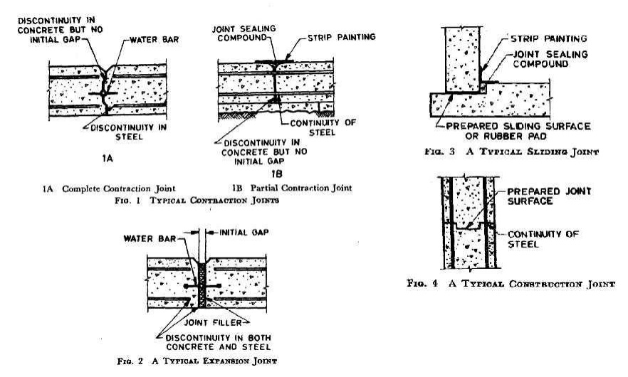
a) Movetnent Joints -
There are three categories of movement joints:
contraction joint - A
movement joint with a deliberate discontinuity but no initial gap between the
concrete on either side of the joint, the joint being intended to accommodate
contraction of the concrete ( see Fig. 1 ).
A distinction should be
made between a complete contraction joint (see Fig. 1A ) in which both concrete
and reinforcing steel are interrupted, and a partial contraction joint (. see
Fig. 1B ) in which only the concrete is interrupted, the reinforcing steel
running through.
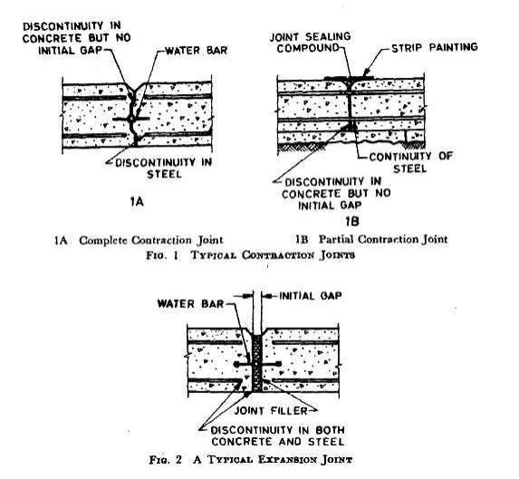
Expansion joint -
A movement joint with complete discontinuity in both reinforcement and
concrete and intended to accommodate either expansion or contraction of the
structure (see Pig. 2).
In general, such a
joint requires the provision of an initial gap between the adjoining parts of a
structure which by closing or opening accommodates the expansion or contraction
of the structure. Design of the joint so as to incorporate sliding surfaces, is
not, however, precluded and may sometimes be advantageous.
b)
Construction Joint-A joint in the concrete introduced for convenience in
construction at which special measures are taken to achieve subsequent
continuity without provision for further relative movement, is called a
construction joint. A typical application is between successive lifts in a
reservoir.
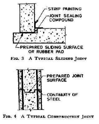
The position and
arrangement of all construction joints should be predetermined by the engineer.
Consideration should be given to limiting the number of such joints and to
keeping them free from possibility of percolations in a similar manner to
contraction joints.
c) Temporary Open
Joints - A gap temporarily left between the concrete of adjoining
parts of a structure which after a suitable interval and before the structure
is put into use, is filled with mortar or concrete either completely (
Fig. 5A) or as provided below, with the inclusion of suitable jointing
materials ( Fig. 5B and SC). In the former case the width of the gap should be
sufficient to allow the sides to be prepared before filling.
Where
measures are taken for example, by the inclusion of suitable jointing materials
to maintain the water tightness of the concrete subsequent to the filling of
the joint, this type of joint may be regarded as being equivalent to a
contraction joint ( partial or complete ) as defined above.
(b) Design the circular tank (only procedure.
in the construction of concrete
structures for the storage of liquids, the imperviousness of concrete is an
important basic requirement. Hence, the design of such construction is based on
avoidance of cracking in the concrete. The structures are prestressed to avoid
tension in the concrete. In addition, prestressed concrete tanks require low
maintenance. The resistance to seismic forces is also satisfactory.
Prestressed concrete tanks are used in water
treatment and distribution systems, waste water collection and treatment system
and storm water management. Other applications are liquefied natural gas (LNG)
containment structures, large industrial process tanks and bulk storage tanks.
The construction of the tanks is in the following sequence. First, the concrete
core is cast and cured. The surface is prepared by sand or hydro blasting.
Next, the circumferential prestressing is applied by strand wrapping machine.
Shotcrete is applied to provide a coat of concrete over the prestressing
strands.
Analysis
The analysis of liquid
storage tanks can be done by IS:3370 - 1967,
Part 4, or by the finite element method. The Code provides
coefficients for bending moment, shear and hoop tension (for cylindrical
tanks), which were developed from the theory of plates and shells. In Part 4, both rectangular and cylindrical tanks
are covered. Since circular prestressing is applicable to cylindrical tanks,
only this type of tank is covered in this module.
The following types of boundary conditions are
considered in the analysis of the cylindrical wall.
a) For
base: fixed or hinged
b) For
top: free or hinged or framed.
For
base
Fixed: When the wall is built continuous with its
footing, then the base can be considered to be fixed as the first
approximation.
Hinged: If the sub
grade is susceptible to settlement, then a hinged base is a conservative
assumption. Since the actual rotational restraint from the footing is somewhere
in between fixed and hinged, a hinged base can be assumed.
The base can be made
sliding with appropriate polyvinyl chloride (PVC) water-stops for liquid
tightness.
For top
Free: The top of the
wall is considered free when there is no restraint in expansion. Hinged: When
the top is connected to the roof slab by dowels for shear transfer, the
boundary condition can be considered to be hinged.
Framed: When the top of
the wall and the roof slab are made continuous with moment transfer, the top is
considered to be framed. The hydrostatic pressure on the wall increases
linearly from the top to the bottom of the liquid of maximum possible depth. If
the vapour pressure in the free board is negligible, then the pressure at the
top is zero. Else, it is added to the pressure of the liquid throughout the
depth. The forces generated in the tank due to circumferential prestress are
opposite in nature to that due to hydrostatic pressure. If the tank is built
underground, then the earth pressure needs to be considered. The hoop tension
in the wall, generated due to a triangular hydrostatic pressure is given as
follows.
The hoop tension in the
wall, generated due to a triangular hydrostatic pressure is given as follows.
T = CT w H Ri (9-6.15)
The bending moment in the vertical direction is
given as follows. M = CM w H3 (9-6.16)
The shear at the base is given by the following
expression. V = CV w H2 (9-6.17)
In
the previous equations, the notations used are as follows. CT = coefficient for
hoop tension
CM = coefficient for bending moment CV = coefficient
for shear
w = unit weight of liquid H = height of the liquid
Ri = inner radius of the wall.
The values of the
coefficients are tabulated in IS:3370 - 1967, Part
4, for various values of H2/Dt, at different depths of the liquid. D
and t represent the inner diameter and the thickness of the wall, respectively.
The typical variations of CT and CM with depth, for two sets of boundary
conditions are illustrated.
The roof can be made of
a dome supported at the edges on the cylindrical wall. Else, the roof can be a
flat slab supported on columns along with the edges.
IS:3370 - 1967, Part 4,
provides coefficients for the analysis of the floor and roof
slabs.
Design
IS:3370 - 1967, Part 3,
provides design requirements for prestressed tanks. A few
of them are mentioned.
1)
The computed stress in the concrete and
steel, during transfer, handling and construction, and under working loads,
should be within the permissible values as specified in IS:1343 - 1980.
2) The
liquid retaining face should be checked against cracking with a load factor of
1.2. ?CL/?WL ?1.2 (9-6.18)
Here,
?CL = stress under cracking load
?WL = stress under working load.
Values of limiting tensile strength of concrete for
estimating the cracking load are Specified in the Code.
3) The
ultimate load at failure should not be less than twice the working load.
When the tank is full, there should be compression
in the concrete at all points of at least 0.7 N/mm2. When the tank is empty,
there should not be tensile stress greater than 1.0 N/mm2. Thus, the tank
should be analysed both for the full and empty conditions.
5) There should be provisions to allow for elastic
distortion of the structure during prestressing. Any restraint that may lead to
the reduction of the prestressing force, should be considered.
Related Topics