Chapter: Mechanical : Advanced IC Engines : Spark Ignition Engines
Design of carburettor

Design of carburettor
Carburetor Fundamentals
A
carburetor has been the most common device used to control the fuel flow in to
the intake manifold and distribute the fuel across the air stream. In a
carburetor the air flows through a converging-diverging nozzle called a venturi.
The pressure difference set up between the carburetor inlet and the throat of
the nozzle (which depends on the air flow rate) is used to meter the
appropriate fuel flow for that air flow. The fuel enters the air stream through
the fuel discharge tube or ports in the carburetor body and is atomized and
convected by the air stream past the throttle plate and into the intake
manifold. Fuel evaporation starts within the Carburetor and continues in the
manifold as fuel droplets move with the air flow and as liquid fuel folks over
the throttle and along the manifold walls. A modem carburetor which meters, the
appropriate fuel flow into the air stream over the complete engine operating
range is a highly developed and complex device. There are many types of carburetors;
they share the same basic concepts which we will now examine.
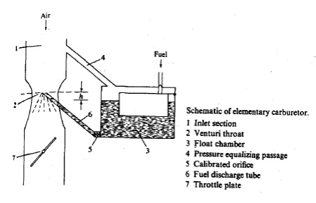
Figure
shows the essential components of an elementary carburetor. The air enters the
intake section of the carburetor (1) from the air cleaner which removes
suspended dust particles. The air then flows into the carburetor venture (a
converging-diverging nozzle) (2) where the air velocity increases and the
pressure decrease. The fuel level is maintained at a constant height in the
float chamber (3) which is connected 'via an air duct (4) to the carburetor
intake section
(I). The
fuel flows through the main jet (a calibrated orifice) (5) as a result of the
pressure difference between the float chamber and the venturi throat and
through the fuel discharge nozzle (6) into the venturi throat where the air
stream atomizes the liquid fuel. The fuel-air mixture flows through the
diverging section of the venturi where the flow decelerates and some pressure
recovery occurs. The flow then passes the throttle valve (7) and enters the
intake manifold. Note that the flow may be unsteady even when engine load and
speed are Constant, due- to the periodic filling of each of the engine cylinder
which draws air through the carburetor venturi. The induction time, 1/(2N) (20
ms at 1500 rev / min) is the characteristic time of this periodic cylinder
filling process. Generally, the characteristic times of changes in throttle
setting are longer; it takes several engines operating cycles to re-establish
steady-state engine operation after a sudden change in throttle position. It is
usually assumed that the flow processes in the carburetor can be modelled as
quasi steady.
Related Topics