Chapter: Civil Engineering : Building Components and Structures
Conventional spread footings: R.C.C. footings and Grillage footing
Conventional spread footings
This type of
foundations is commonly used for walls and masonry columns. These foundations
are built after opening the trenches to required depth. Such footings are
economical up to a maximum depth of 3 m. As these foundations are suitable
depth, they are grouped under shallow foundations.
Figure 2.2.1 shows
a conventional spread footing for a wall and Fig. 2.2.2 shows it for a masonry
column.
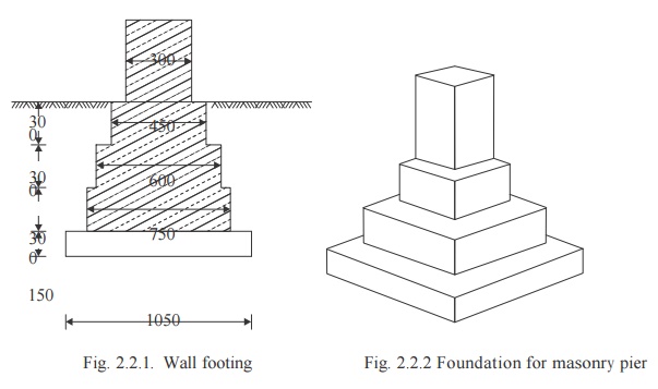
Fig. 2.2.1. Wall footing Fig. 2.2.2 Foundation for masonry pier
Before building
these footing trenches are opened to required depth and the soil is rammed
well. Then a plain concrete of mix 1 : 4 : 8 is provided. Its thickness varies
from 150 to 200 mm. Over this bed, stone masonry footing is built. It is built
in courses each course projecting 50 to 75 mm from the top course and height of
each course being 150 to 200 mm. In case of wall footing the projections are
only one direction while in case of columns, they are in both directions. The
projection of bed concrete from the lowest course of foundation masonry is
usually 150 mm.
R.C.C. footings
There are mainly two types of R.C.C. footings:
1.
One way reinforced footings.
2.
Two way reinforced footings.
1. One Way Reinforced Footing: These
footings are for the walls. In these footings main reinforcements are in
the transverse direction of wall. In longitudinal directions there will be only
nominal reinforcement.
2. Two Way Reinforced Footings: For columns
two way reinforced footings are provided. The following types of the
footings are common:
(i) Isolated Column Footings:
If separate footings are provided for each column, it is
called isolated column footing. Figure 2.2.2.1 shows a typical isolated column
footing. The size of footing is based on the area required to distribute the
load of the columns safely over the soil .These footings are provided over a
100 to 150 mm bed concrete. Required reinforcements and thickness of footing
are
found by the design engineers. Thickness may be uniform or
varying.
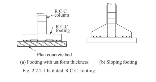
(a) Footing with uniform thickness (b) Sloping footing
Fig. 2.2.2.1 Isolated R.C.C. footing
(ii) Combined Footings: Common footings may be provided for two columns. This
type of footing is necessary when a column is very close to the boundary of the
property and hence there is no scope to project footing much beyond the column
face. Figure 2.2.2.2 shows a typical combined footing. The footing is to be
designed for transferring loads from both columns safely to the soil. The two
columns may or may not be connected by a strap beam.
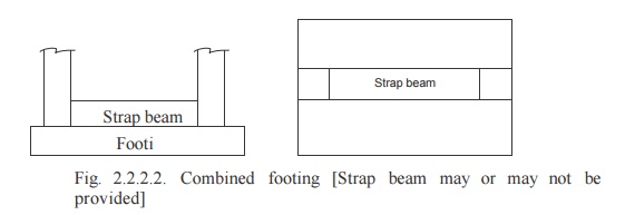
Fig. 2.2.2.2. Combined footing [Strap beam may
or may not be provided]
(iii) Continuous Footings: If a footing is common to more than two columns in a row, it is called continuous footing. This type of footing is necessary, if the columns in a row are closer or if SBC of soilis low. Figure 2.2.2.3shows this type of footing.

Fig.2.2.2.3
Continuous footing
(iv) Mat Footing/Raft
Footing: If the load on the column is quite high
(Multistorey columns) or when the SBC of soil is low, the sizes of
isolated columns may work out to be to such an extent that they overlap each
other. In such situation a common footing may be provided to several columns as
shown in Fig. 2.2.2.4 Such footings are known as raft footings.
If the beams are provided in both directions
over the footing slab for connecting columns, the raft foundations may be
called as grid foundation also.
The added advantage of such footing is,
settlement is uniform and hence unnecessary stresses are not produced.
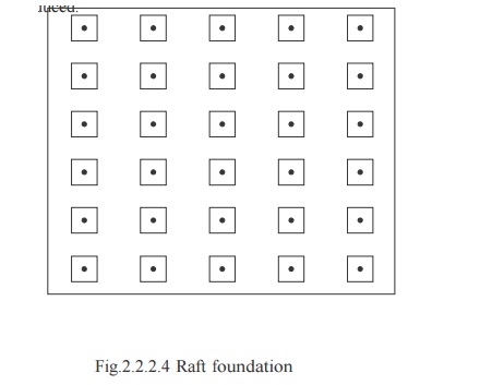
Fig.2.2.2.4 Raft foundation
Grillage footing
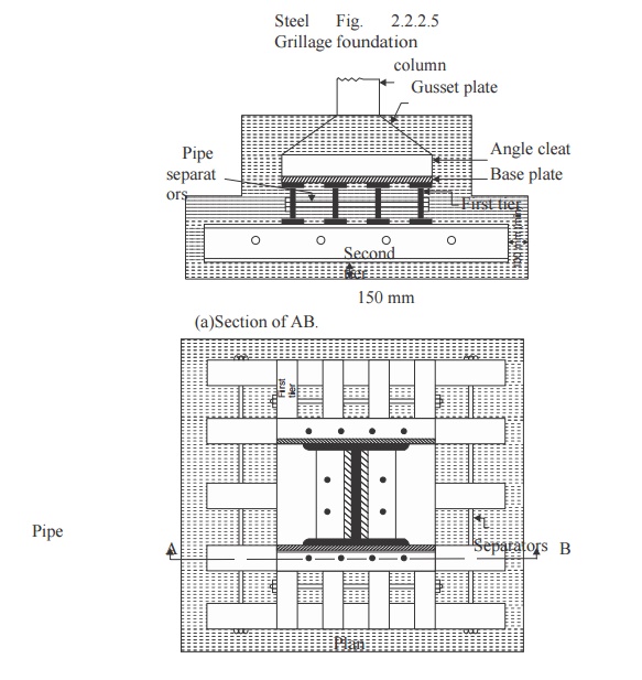
High rise buildings are built with steel columns
encased in concrete. Such columns carry very heavy load and hence they need
special foundations to spread the load to a larger area of soil. Grillage
foundation is one such special foundation. It consists of one tier or more
tiers of I-sections steel beams. Fig 2.2.2.5 shows a typical two tier grillage
foundation. Top tier consists of less number but large size steel section while
lower tier consists of larger number but smaller size steel sections. Column
load is transferred to the top tier through a base plate. The grillage beams
are unpainted and are encased in concrete with minimum cover of 100 mm beyond
the edges of steel sections. A minimum clear space of 75 mm should be
maintained between the flanges of adjacent grillage beams so that concreting
can be made properly.To maintain spacing, pipe separators are used.
Steel Fig. 2.2.2.5 Grillage foundation
Related Topics