Chapter: Communication Theory : Noise Characterisation
Classification of Noise
CLASSIFICATION OF NOISE:
Noise is
random, undesirable electrical energy that enters the communications system via
the communicating medium and interferes with the transmitted message. However,
some noise is also produced in the receiver.
(OR)
With
reference to an electrical system, noise may be defined as any unwanted form of
energy which tends to interfere with proper reception and reproduction of
wanted signal.
Noise may
be put into following two categories.
1. External noises, i.e. noise whose sources are
external. External noise may be
classified into the following three types:
·
Atmospheric
noises
·
Extraterrestrial
noises
·
Man-made
noises or industrial noises.
2. Internal noise in communication, i.e.
noises which get, generated within the receiver or communication system. Internal noise may be put into the following
four categories.
·
Thermal
noise or white noise or Johnson noise
·
Shot
noise.
·
Transit
time noise
·
Miscellaneous
internal noise.
External
noise cannot be reduced except by changing the location of the receiver or the
entire system. Internal noise on the other hand can be easily evaluated
mathematically and can be reduced to a great extent by proper design. As
already said, because of the fact that internal noise can be reduced to a great
extent, study of noise characteristics is a very important part of the
communication engineering.
1. Explanation of External Noise
·
Atmospheric
Noise:
Atmospheric
noise or static is caused by lighting discharges in thunderstorms and other
natural electrical disturbances occurring in the atmosphere. These electrical
impulses are random in nature. Hence the energy is spread over the complete
frequency spectrum used for radio communication.
Atmospheric
noise accordingly consists of spurious radio signals with components spread
over a wide frequency range. These spurious radio waves constituting the noise
get propagated over the earth in the same fashion as the desired radio waves of
the same frequency. Accordingly at a given receiving point, the receiving
antenna picks up not only the signal but also the static from all the
thunderstorms, local or remote.
ü Extraterrestrial noise:
·
Solar noise
·
Cosmic noise
Ø Solar noise:
Ø Cosmic noise:
Distant
stars are also suns and have high temperatures. These stars, therefore, radiate
noise in the same way as our sun. The noise received from these distant stars
is thermal noise (or black body noise) and is distributing almost uniformly
over the entire sky. We also receive noise from the center of our own galaxy
(The Milky Way) from other distant galaxies and from other virtual point
sources such as quasars and pulsars.
Ø Man-Made Noise (Industrial Noise):
2. Explanation of Internal Noise in
communication:
·
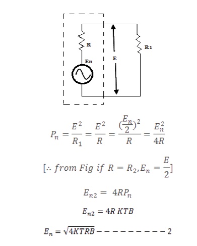
Thermal
Noise:

Where Pn
= Maximum noise power output of a resistor.
K = Boltzmann‘s constant = 1.38 x10⁻²³ joules I Kelvin.
T = Absolute temperature.
B = Bandwidth over which noise is measured.

·
Transit
Time Noise:
Another
kind of noise that occurs in transistors is called transit time noise.
Transit
time is the duration of time that it takes for a current carrier such as a hole
or current to move from the input to the output.
The
devices themselves are very tiny, so the distances involved are minimal. Yet
the time it takes for the current carriers to move even a short distance is
finite. At low frequencies this time is negligible. But when the frequency of
operation is high and the signal being processed is the magnitude as the
transit time, then problem can occur. The transit time shows up as a kind of
random noise within the device, and this is directly proportional to the
frequency of operation.
·
Miscellaneous
Internal Noises Flicker Noise:
Flicker
noise or modulation noise is the one appearing in transistors operating at low
audio frequencies. Flicker noise is proportional to the emitter current and
junction temperature. However, this noise is inversely proportional to the
frequency. Hence it may be neglected at frequencies above about 500 Hz and it,
Therefore, possess no serious problem.
·
Transistor
Thermal Noise:
Within the transistor, thermal noise is caused by
the emitter, base and collector internal
resistances. Out of these three regions, the base region contributes maximum
thermal noise.
·
Partition
Noise:
Partition
noise occurs whenever current has to divide between two or more paths, and
results from the random fluctuations in the division. It would be expected,
therefore, that a diode would be less noisy than a transistor (all other
factors being equal) If the third electrode draws current (i.e.., the base
current). It is for this reason that the inputs of microwave receivers are
often taken directly to diode mixers.
·
Shot
Noise:
The most
common type of noise is referred to as shot noise which is produced by the
random arrival of 'electrons or holes at the output element, at the plate in a
tube, or at the collector or drain in a transistor. Shot noise is also produced
by the random movement of electrons or holes across a PN junction. Even through
current flow is established by external bias voltages, there will still be some
random movement of electrons or holes due to discontinuities in the device. An
example of such a discontinuity is the contact between the copper lead and the
semiconductor materials. The interface between the two creates a discontinuity
that causes random movement of the current carriers.
3. Signal
to Noise Ratio:
Noise is
usually expressed as a power because the received signal is also expressed in
terms of power. By Knowing the signal to noise powers the signal to noise ratio
can be computed. Rather than express the signal to noise ratio as simply a
number, you will usually see it expressed in terms of decibels.

A
receiver has an input signal power of l.2µW. The noise power is 0.80µW. The
signal to noise ratio is
Signal to
Noise Ratio = 10 Log (1.2/0.8)
= 10 log
1.5
= 10 (0.176)
= 1.76 Db

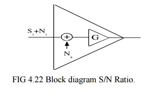
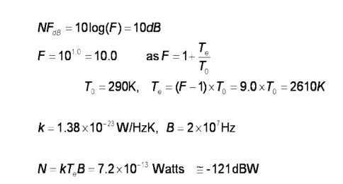
4. Noise Figure:
Noise
Figure is designed as the ratio of the signal-to-noise power at the input to
the signal to noise power at the output.The device under consideration can be
the entire receiver or a single amplifier stage. The noise figure also called
the noise factor can be computed with the expression , F = Signal to Noise
power Input/Signal to noise power output .You can express the noise figure as a
number, more often you will see it expressed in decibels.

Related Topics