Chapter: Mechanical : Engineering Thermodynamics : Properties of a Pure Substance and Steam Power Cycle
Brayton cycle, Rankine Cycle, Otto Cycle
BRAYTON CYCLE
The Brayton cycle is widely used as the basis for the operation of Gas turbine. A schematic diagram of a simple gas turbine (open cycle) and the corresponding p-v and T-s diagrams are shown below. Air is drawn from he atmosphere into compressor, where it is compressed reversibly and adiabatically. The relative high pressure air is then used in burning the fuel in the combustion chamber. The air-fuel ratio quite high (about 60:1) to limit the temperature burnt gases entering the turbine. The gases then expand isentropically in the turbine. A portion of the work obtained from the turbine is utilised to drive the compressor and the auxiliary drive and the rest of the power output is the net power of the gas turbine plant.
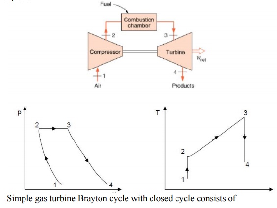
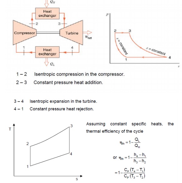
Simple gas turbine Brayton cycle with closed cycle consists of

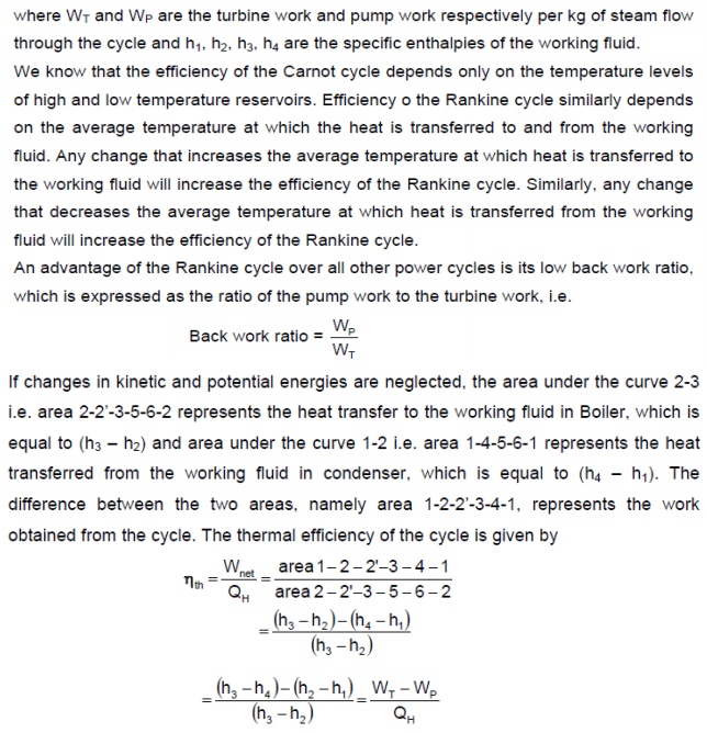
RANKINE CYCLE
COMBINED CYCLE
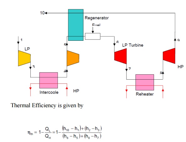
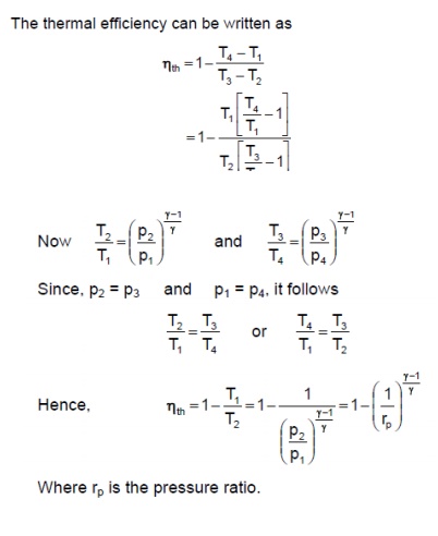
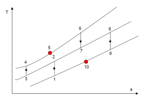
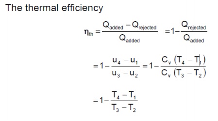
Thermal Efficiency is given as above.
OTTO CYCLE
The air standard Otto Cycle is an idealised cycle which closely approximates the operation of Spark Ignition (SI) Engine.
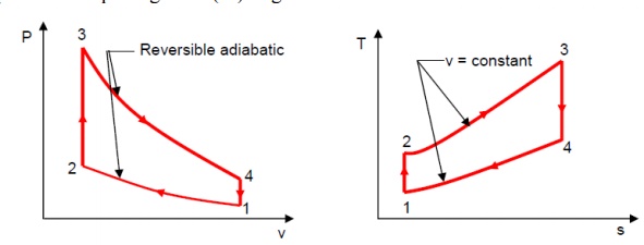
Process 1-2 is reversible adiabatic (isentropic) compression of air when the piston moves from crank-end dead centre (BDC) to cylinder head dead centre (TDC). During the process 2-3, heat is transferred reversibly to the system at constant volume (this process corresponds to the spark ignition of the actual engine). The curve 3-4 represents the reversible adiabatic expansion process when piston moves from TDC to BDC and the curve 4-1 represents the heat rejected by the system reversibly at constant volume.
Related Topics